
Toyota Sienna Service Manual: Display check mode
HINT:
- This mode checks the color display on the display.
- Illustrations may differ from the actual vehicle depending on the device settings and options. Therefore, some detailed areas may not be shown exactly the same as on the actual vehicle.
1. ENTER DIAGNOSTIC MODE
2. DISPLAY CHECK
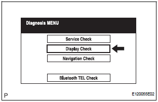
- Select "Display Check" from the "Diagnosis MENU" screen.
3. COLOR BAR CHECK
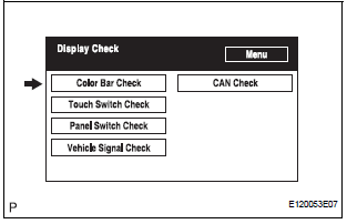
- Select "Color Bar Check" from the "Display Check" screen.
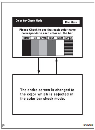
- Select a color bar from the "Color Bar Check Mode" screen.
- Check the display color.
HINT:
- The entire screen turns to the color or stripe selected.
- Touching the display will return to the "Color Bar Check" screen.
4. TOUCH SWITCH CHECK
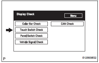
- Select "Touch Switch Check" from the "Display Check" screen.
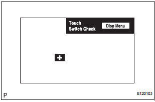
- Touch the display anywhere in the open area to perform the check when the "Touch Switch Check" screen is displayed.
HINT:
- A "+" mark is displayed where the display is touched.
- The "+" mark remains on the display even after the finger is removed.
5. PANEL SWITCH CHECK
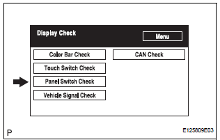
- Select "Panel Switch Check" from the "Display Check" screen.
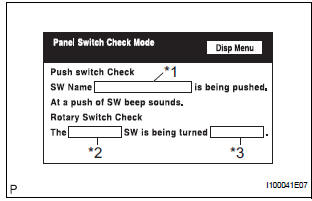
- Operate each switch and check that the switch name and condition are correctly displayed
|
Display |
Contents |
| Push switch name/*1 |
|
| Rotary switch name/*2 | Name of the rotary switch is displayed |
| Rotary switch direction/*3 | Direction of the rotary switch is displayed. |
6. VEHICLE SIGNAL CHECK
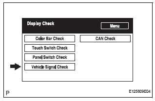
- Select "Vehicle Signal Check" from the "Display Check" screen.
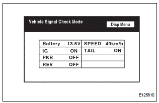
- When the "Vehicle Signal Check Mode" screen is displayed, check all the vehicle signal conditions.
HINT:
- Only conditions having inputs are displayed.
- This screen is updated once per second when input signals to the vehicle are changed.
- For details of this function, refer to DIAGNOSIS DISPLAY DETAILED DESCRIPTION.
7. CAN CHECK
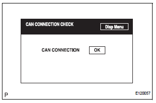
- Select "CAN check" from the "Display check" screen.
- Check the CAN connection check result.
HINT:
- This function operates only for the systems connected to the CAN system.
- For details of this function, refer to DIAGNOSIS DISPLAY DETAILED DESCRIPTION
 System normal condition check
1. CHECK NORMAL CONDITION
If the symptom is applicable to any of the following,
it is intended behavior, and not a malfunction.
Symptom
Answer
A longer route ...
 Bluetooth tel check mode
HINT:
Illustration may differ from the actual vehicle depending on
the device settings and options. Therefore, some detailed
area may not be shown exactly the same as on the actual
vehicle.
1. EN ...
Other materials:
Driving tips
Winter driving tips
Carry out the necessary preparations and inspections before
driving the vehicle in winter. Always drive the vehicle in a manner
appropriate to the prevailing weather conditions.
Preparation for winter
Use fluids that are appropriate to the prevailing outside temperatures. ...
Inspection
1. INSPECT CHARCOAL CANISTER ASSEMBLY
(a) Visually check the charcoal canister for cracks or
damage.
If cracks or damage are found, replace the charcoal
canister assembly.
(b) Check charcoal canister operation.
(1) With the purge port closed, blow 1.67 kPa (17.0
gf/cm2, 0.24 psi) ...
Terminals of ECU
1. INSTRUMENT PANEL JUNCTION BLOCK
(MULTIPLEX NETWORK BODY ECU)
Disconnect the B6, B7 and B9 ECU connectors.
Disconnect the 1A, 1C, 1K, 1L and 1P J/B
connectors.
Check the voltage or resistance according to the
value(s) in the table below (wire harness side
connector).
...
