Toyota Sienna Service Manual: Display Signal Circuit between Television Display Assembly and Radio and Navigation Assembly
DESCRIPTION
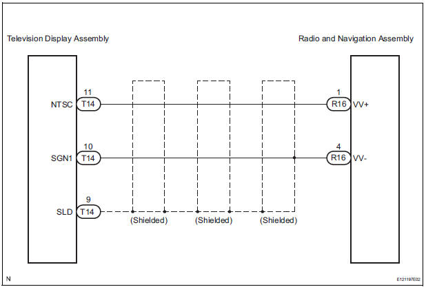
This circuit sends a DVD image signal from the television display assembly to the radio and navigation assembly.
WIRING DIAGRAM
INSPECTION PROCEDURE
1 CHECK HARNESS AND CONNECTOR (RADIO AND NAVIGATION ASSEMBLY - TELEVISION DISPLAY ASSEMBLY)
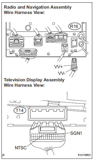
- Disconnect the radio and navigation assembly connector R16 and television display assembly connector T14.
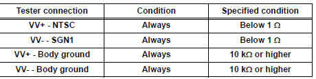
- Measure the resistance according to the value(s) in the table below.
Standard resistance
2 INSPECT TELEVISION DISPLAY ASSEMBLY
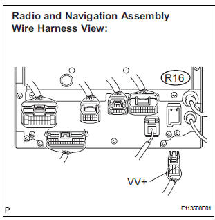
- Reconnect the television display assembly connector R16.
- Measure the waveform according to the table below.
OK
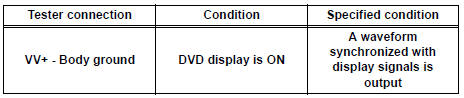
HINT: The waveform pattern may differ from that shown in the illustration below due to differences in oscilloscope setting. A normal television display assembly operating condition can be determined if any waveform is output.
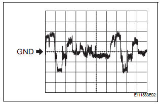
- Oscilloscope waveform
- Terminal: VV+ - Body groun
Setting: 200 mV/DIV., 10 μs/DIV.
Condition: DVD display is ON.
PROCEED TO NEXT CIRCUIT INSPECTION SHOWN IN PROBLEM SYMPTOMS TABLE
 Navigation Voice Circuit
DESCRIPTION
This circuit is used when the voice guidance in the navigation system is on.
WIRING DIAGRAM
INSPECTION PROCEDURE
1 CHECK HARNESS AND CONNECTOR (RADIO AND NAVIGATION ASSEMBLY - STER ...
 Microphone Circuit between Microphone and Radio and Navigation
Assembly
Microphone Circuit between Microphone and Radio and Navigation
Assembly
DESCRIPTION
This circuit sends a microphone signal from the microphone to the radio and
navigation assembly.
It also supplies power from the radio and navigation assembly to the microphone.
WIR ...
Other materials:
Tire size
Typical tire size information
The illustration indicates typical tire size.
Tire use
(P = Passenger car,
T = Temporary use)
Section width (millimeters)
Aspect ratio
(tire height to section width)
Tire construction code
(R = Radial, D = Diagonal)
Wheel diameter (inches)
...
Preparation 2gr-fe cooling
SST
RECOMMENDED TOOLS
EQUIPMENT
COOLANT
Capacity
Classification
11.3 liters (12.0 US qts, 10.0 Imp. qts)
Use only "TOYOTA Super Long Life Coolant" or similar high quality
ethylene glycol based non-silicate, non-amine, non-nitrite, non-borate
coolant ...
Axle
SST
RECOMMENDED TOOLS
HINT:
Trox is a registered trademark of Trxtron Inc.
EQUIPMENT
...
