Toyota Sienna Service Manual: Microphone Circuit between Microphone and Radio and Navigation Assembly
DESCRIPTION
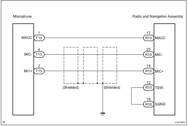
This circuit sends a microphone signal from the microphone to the radio and navigation assembly.
It also supplies power from the radio and navigation assembly to the microphone.
WIRING DIAGRAM
INSPECTION PROCEDURE
1 INSPECT RADIO AND NAVIGATION ASSEMBLY
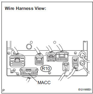
- Measure the voltage according to the value(s) in the table below.
Standard voltage
2 CHECK HARNESS AND CONNECTOR
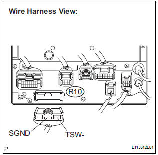
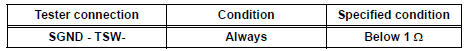
- Disconnect the radio and navigation assembly connector R10.
- Measure the resistance according to the value(s) in the table below.
Standard resistance
3 CHECK HARNESS AND CONNECTOR (MICROPHONE - RADIO AND NAVIGATION ASSEMBLY)

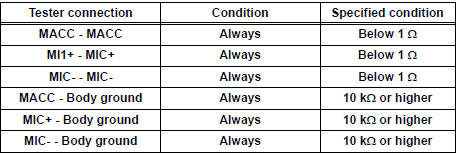
- Disconnect the microphone connector T13 and radio and navigation assembly connector R10.
- Measure the resistance according to the value(s) in the table below.
Standard resistance
PROCEED TO NEXT CIRCUIT INSPECTION SHOWN IN PROBLEM SYMPTOMS TABLE
 Display Signal Circuit between Television Display Assembly and Radio
and Navigation Assembly
Display Signal Circuit between Television Display Assembly and Radio
and Navigation Assembly
DESCRIPTION
This circuit sends a DVD image signal from the television display assembly to
the radio and navigation
assembly.
WIRING DIAGRAM
INSPECTION PROCEDURE
1 CHECK HARNESS AND CONNECTO ...
 Stereo Component Amplifier Communication Error
INSPECTION PROCEDURE
1 IDENTIFY THE COMPONENT SHOWN BY THE SUB-CODE
Enter the diagnostic mode.
Press the "LAN Mon" switch to change to "LAN Monitor"
mode.
&nbs ...
Other materials:
Description of code registration
It is necessary to register the transmitter ID in the tire
pressure warning ECU when replacing the tire pressure
warning valve and transmitter and/or tire pressure
warning ECU.
(a) Before registration
(1) In case of tire pressure warning ECU
replacement.
Read the registered transmitter I ...
Installation
1. INSTALL STARTER ASSEMBLY
(a) Install the starter with the 2 bolts.
Torque: 37 N*m (380 kgf*cm, 26 ft.*lbf) for bolt
(b) Connect the starter connector.
(c) Install the terminal nut and cover the nut with the
cap.
Torque: 9.8 N*m (100 kgf*cm, 7 ft.*lbf) for nut
2. INSTALL NO. 1 ...
Removal
HINT:
Remove the RH side by the same procedure as the LH side.
1. REMOVE REAR WHEEL
2. REMOVE QUARTER TRIM PANEL ASSEMBLY
FRONT LH
HINT:
Remove the LH side by the same procedure as the RH
side (See page IR-9).
3. REMOVE REAR SPEED SENSOR
(a) Disconnect the speed sensor connector, and pu ...
