Toyota Sienna Service Manual: Parking Brake Switch Circuit
DESCRIPTION
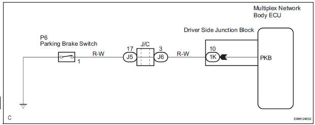
The Multiplex network body ECU receives parking brake switch signal.
WIRING DIAGRAM
INSPECTION PROCEDURE
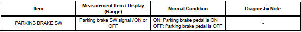
1 READ VALUE OF INTELLIGENT TESTER
- Connect the intelligent tester to DLC3.
- Turn the ignition switch ON and push the intelligent tester main switch ON.
- Select the items below in the DATA LIST, and read the displays on the intelligent tester.
BODY NO.1:
2 INSPECT PARKING BRAKE SWITCH ASSEMBLY
- Check that there is resistance between the terminal and the body ground when parking brake switch is operated.
Resistance:
ON (When shaft is pressed): No continuity:
10 kΩ or higher
OFF (When shaft is not pressed): Continuity:
Below 1 Ω
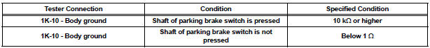
3 CHECK HARNESS AND CONNECTOR
- Disconnect the 1K connector from instrument panel junction block assembly
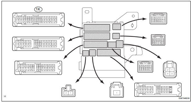
- Check the resistance between the terminal 1K-10 of the instrument panel junction block assembly connector side and body ground
PROCEED TO NEXT CIRCUIT INSPECTION SHOWN IN PROBLEM SYMPTOMS TABLE
 Illumination Circuit
DESCRIPTION
The Multiplex network body ECU controls illumination light as shown in the
chart below.
Room light assembly (Interior light, luggage component light) and
courtesy light wit ...
 Taillight Relay Circuit
DESCRIPTION
The Multiplex network body ECU controls TAIL relay when signal is received
from headlight dimmer
switch assembly.
WIRING DIAGRAM
INSPECTION PROCEDURE
1 PERFORM ACTIVE TEST BY IN ...
Other materials:
Dtc check / clear
1. DTC CHECK/CLEAR (WHEN USING INTELLIGENT TESTER):
(a) DTC check
(1) Connect the intelligent tester to the DLC3.
(2) Turn the ignition switch to the ON position.
(3) Read the DTCs following the prompts on the
tester screen.
(b) DTC clear
(1) Connect the intelligent tester to the DLC3 ...
Throttle Actuator Control Throttle Body Range /
Performance
DTC P2119 Throttle Actuator Control Throttle Body Range /
Performance
DESCRIPTION
The Electronic Throttle Control System (ETCS) is composed of the throttle
actuator, Throttle Position (TP)
sensor, Accelerator Pedal Position (APP) sensor, and ECM. The ECM operates the
throttle actuator to
re ...
DTC check / clear
NOTICE:
All the stored DTCs and freeze frame data are erased if:
the ECM is changed from normal mode to check mode
or vice versa; or 2) the ignition switch is turned from ON
to ACC or off while in check mode.
Before changing modes, always check and make a note
of any DTCs and fr ...
