Toyota Sienna Service Manual: Driver Side Outer Mirror
DTC B1209 Driver Side Outer Mirror
DESCRIPTION
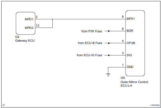
This DTC is detected when communication between the outer mirror control ECU LH and multiplex network gateway ECU stops for more than 10 seconds
|
DTC No. |
DTC Detection Condition |
Trouble Area |
|
B1209 |
Driver side outer mirror ECU communication stops |
|
WIRING DIAGRAM
INSPECTION PROCEDURE
1 CHECK HARNESS AND CONNECTOR (OUTER MIRROR CONTROL ECU LH - BATTERY)
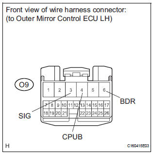
- Disconnect the O9 ECU connector.
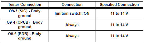
- Measure the voltage according to the value(s) in the table below.
Standard voltage
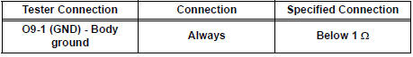
2 CHECK HARNESS AND CONNECTOR (OUTER MIRROR CONTROL ECU LH - GROUND)
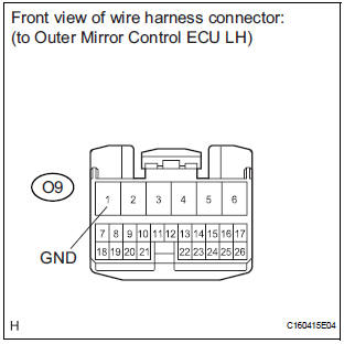
- Measure the resistance according to the value(s) in the table below.
Standard resistance
3 CHECK COMMUNICATION LINE
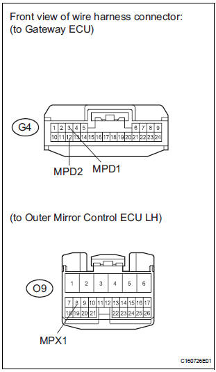
- Disconnect the G4 ECU connector.
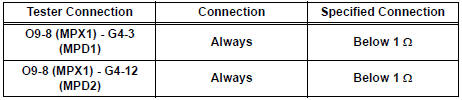
- Measure the resistance according to the value(s) in the table below.
Standard resistance
Result
REPLACE OUTER MIRROR CONTROL ECU LH
 Passenger Side Outer Mirror ECU
DTC B1208 Passenger Side Outer Mirror ECU
DESCRIPTION
This DTC is detected when communication between the outer mirror control ECU
RH and multiplex
network gateway ECU stops for more than 10 seco ...
 Short to B+ in Door System Communication
Bus Malfunction/ Short to GND in Door System Communication
Bus Malfunction
Short to B+ in Door System Communication
Bus Malfunction/ Short to GND in Door System Communication
Bus Malfunction
DTC B1214 Short to B+ in Door System Communication
Bus Malfunction
DTC B1215 Short to GND in Door System Communication
Bus Malfunction
DESCRIPTION
DTCs B1214 and B1215 are output when a short to ...
Other materials:
Open in ABS Motor Relay Circuit
DESCRIPTION
The ABS motor relay supplies power to the ABS pump motor. While the ABS is
activated, the ECU turns
the motor relay on and operates the ABS pump motor.
If the voltage supplied to the motor relay (+BM) is below the DTCs detection
threshold due to low voltage
from the battery ...
Using the mechanical key (vehicles with a smart key system)
To take out the mechanical key,
push the release button and take
the key out.
The mechanical key can only be
inserted in one direction, as the
key only has grooves on one side.
If the key cannot be inserted in a
lock cylinder, turn it over and reattempt
to insert it.
After using t ...
Installation
1. INSTALL PARKING BRAKE CONTROL PEDAL ASSEMBLY
(a) Install the parking brake control pedal assembly with
a bolt and the 2 nuts.
Torque: 39 N*m (398 kgf*cm, 29 ft.*lbf)
(b) Connect the parking brake switch connector.
(c) Connect the instrument panel junction block
assembly w/ wiring ha ...
