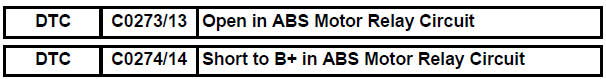
Toyota Sienna Service Manual: Open in ABS Motor Relay Circuit
DESCRIPTION
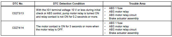
The ABS motor relay supplies power to the ABS pump motor. While the ABS is activated, the ECU turns the motor relay on and operates the ABS pump motor.
If the voltage supplied to the motor relay (+BM) is below the DTCs detection threshold due to low voltage from the battery/alternator, the DTCs may be stored.
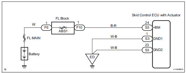
WIRING DIAGRAM
INSPECTION PROCEDURE
HINT: After steps 1, 2 and 3 are completed, start the inspection from step 4 when using the intelligent tester, and from step 5 when not using the intelligent tester.
1 INSPECT FUSE (ABS 1 FUSE)
(a) Remove the ABS 1 fuse from the FL block.
(b) Measure the resistance according to the value(s) in the table below.
Standard resistance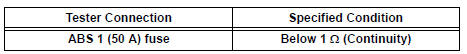


2 INSPECT SKID CONTROL ECU (+BM TERMINAL VOLTAGE)
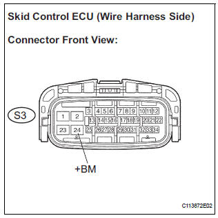
(a) Install the ABS 1 fuse.
(b) Disconnect the skid control ECU connector.
(c) Measure the voltage according to the value(s) in the table below.
Standard voltage 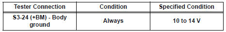

3 INSPECT SKID CONTROL ECU (GND TERMINAL CONTINUITY)
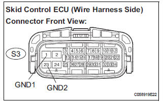
(a) Measure the resistance according to the value(s) in the table below.
Standard resistance 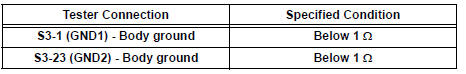

4 PERFORM ACTIVE TEST BY INTELLIGENT TESTER (ABS MOTOR RELAY)
(a) Reconnect the skid control ECU connector.
(b) Connect the intelligent tester to the DLC3.
(c) Turn the ignition switch to the ON position and turn the intelligent tester main switch on.
(d) Start the engine.
(e) Select the ACTIVE TEST mode on the intelligent tester.
ABS: 
(f) Check operating sound of the ABS motor when operating it with the intelligent tester.
OK: The operating sound of the ABS motor is heard.


5 RECONFIRM DTC
(a) Clear the DTCs (See page BC-10).
(b) Start the engine.
(c) Drive the vehicle at the speed of 6 km/h (4 mph) or more.
(d) Check that the same DTCs are recorded (See page BC- 10).
HINT:
- Reinstall the sensors, connectors, etc. and restore the vehicle to its prior condition before rechecking for DTCs.
- If a speed signal of 6 km/h (4 mph) or more is input to the skid control ECU, with the ignition switch on and the stop light switch off, the ECU performs selfdiagnosis of the motor and solenoid circuits.
Result
HINT:
- If any DTCs are output while jiggling a connector or wire harness of the brake actuator (skid control ECU), inspect and repair the connector or wire harness.
- If the normal system code is output, slightly jiggle the connectors, wire harnesses, and fuses of the brake actuator assembly. Make sure that no DTCs are output.
- These DTCs may be stored due to a malfunction in the connector terminal connection, etc.


REPLACE BRAKE ACTUATOR ASSEMBLY
 SFR Solenoid Circuit
DESCRIPTION
The solenoid comes on when signals are received from the ECU and controls the
pressure acting on the
wheel cylinders, thus controlling brake force.
WIRING DIAGRAM
INSPECT ...
 Open in ABS Solenoid Relay Circuit
DESCRIPTION
This relay supplies power to each ABS solenoid.
Immediately after the ignition switch is turned to the ON position, the relay
turns on if the solenoid is
determined to be normal ...
Other materials:
Reassembly
1. INSTALL STRAIGHT PIN
(a) Using a plastic hammer, tap in new straight pins to
the cylinder block.
Standard protrusion
2. INSTALL STUD BOLT
(a) Using E8 and E10 "TORX" sockets, install the stud
bolts.
Torque: 10 N*m (102 kgf*cm, 7 ft.*lbf) for bolt A
17 N*m (173 kgf*cm, ...
Diagnostic trouble code chart
1. DTCS FOR OCCUPANT CLASSIFICATION SYSTEM
If a trouble code is displayed during the DTC check,
check the circuit listed for the code in the table below
(proceed to the page listed for that circuit).
HINT:
When DTC B1150/23 is detected as a result of
troubleshooting for the airbag system, pe ...
System description
1. OUTLINE OF THEFT DETERRENT SYSTEM
When the theft deterrent system detects that the
vehicle is being tampered with, the system sets off
the alarm, causing the horns to sound and the lights
to light up or blink in order to alert people around the
vehicle to the theft.
The ...
