Toyota Sienna Service Manual: Driver Side Seat Belt Warning Light does not Operate
DESCRIPTION
When turning the ignition switch to the ON position, the combination meter assembly communicates with the supplemental restraint system by the multiplex communication system. Unless the driver side seat belt is fastened, the combination meter assembly will turn on the seat belt warning light for driver side. If the driver side seat belt is fastened, then the combination meter assembly will turn off the driver side seat belt warning light.
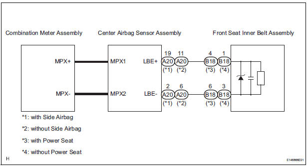
WIRING DIAGRAM
INSPECTION PROCEDURE
1 CHECK MULTIPLEX COMMUNICATION SYSTEM
- Check if the MULTIPLEX communication DTC is output
Result

2 PERFORM ACTIVE TEST BY INTELLIGENT TESTER
- Connect the intelligent tester to the DLC3.
- Turn the ignition switch to the ON position.
- Enter the following menus: DIAGNOSIS / OBD/MOBD / METER / ACTIVE TEST.
- Check the operation by referring to the value(s) in the table below.
METER:

OK: Warning light condition (ON/OFF) can be switched by "ACTIVE TEST".
3 CHECK DTC
- Check if DTC B0126 is output
Result

REPLACE CENTER AIR BAG SENSOR ASSEMBLY
 Engine Coolant Temperature Receiver Gauge Malfunction
DESCRIPTION
The meter CPU receives engine coolant temperature signals from the ECM via
the multiplex
communication lines. The meter CPU displays engine coolant temperature that is
calculated bas ...
 Operating Light Control Rheostat does not Change Light Brightness
DESCRIPTION
The meter CPU receives signals for adjusting illumination on the meter from
this circuit. The meter CPU
detects the illumination level selected by the user according to the position of ...
Other materials:
Lumbar support adjuster assembly
INSPECTION
1. INSPECT LUMBAR SUPPORT ADJUSTER ASSEMBLY
Check operation of the lumbar support adjuster
motor.
Check if the lumbar support adjuster moves
smoothly when the battery is connected to the
lumbar support adjuster motor connector
terminal.
OK
If the r ...
Cranking Holding Function Circuit
DESCRIPTION
The system detects the ignition switch's starting signal (STSW) and then
supplies current to the starter
until the ECM judges that the engine has started successfully. The purpose is to
reduce the holding time
of the ignition key.
WIRING DIAGRAM
Refer to DTC P0617 (See page ...
ACIS Control Circuit
DESCRIPTION
This circuit opens and closes the Intake Air Control Valve (IACV) in response
to changes in the engine
load in order to increase the intake efficiency (ACIS: Acoustic Control
Induction System).
When the engine speed is between 0 and 4450 rpm and the throttle valve opening
angl ...
