Toyota Sienna Service Manual: Evaporative Emission System Switching Valve Control Circuit High
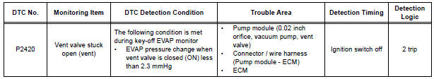
DTC P2420 Evaporative Emission System Switching Valve Control Circuit High
DTC SUMMARY
DESCRIPTION
The circuit description can be found in the EVAP (Evaporative Emission) System.
INSPECTION PROCEDURE
Refer to the EVAP System.
MONITOR DESCRIPTION
5 hours*1 after the ignition switch is turned off, the electric vacuum pump creates negative pressure (vacuum) in the EVAP (Evaporative Emission) system. The ECM monitors for leaks and actuator malfunctions based on the EVAP pressure.
HINT: *1: If the engine coolant temperature is not below 35C (95F) 5 hours after the ignition switch is turned off, the monitor check starts 2 hours later. If it is still not below 35C (95F) 7 hours after the ignition switch is turned off, the monitor check starts 2.5 hours later.
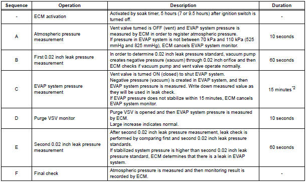
*2: If only a small amount of fuel is in the fuel tank, it takes longer for the EVAP pressure to stabilize.
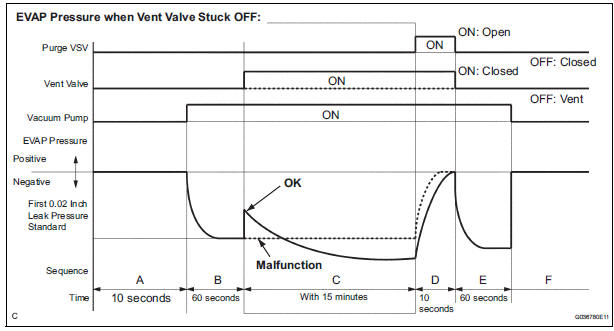
The vent valve turns ON (closes) and the EVAP (Evaporative Emission) system pressure is then measured by the ECM, using the pressure sensor, to conduct an EVAP leak check. If the pressure does not increase when the vent valve is open, the ECM interprets this as the vent valve being stuck open. The ECM illuminates the MIL and sets the DTC.
MONITOR STRATEGY

TYPICAL ENABLING CONDITIONS
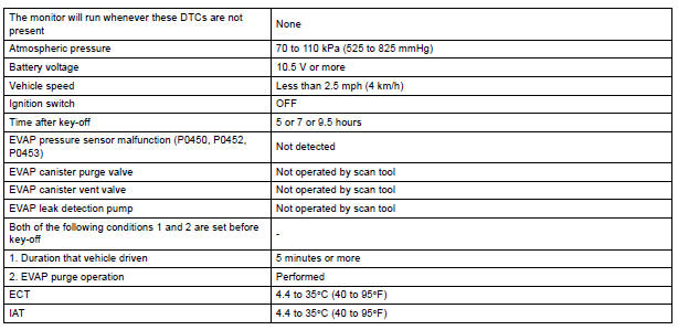
Key-off monitor sequence 1 to 8
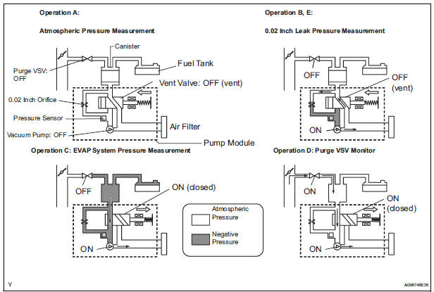
1. Atmospheric pressure measurement

2. First reference pressure measurement
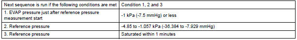
3. EVAP canister vent valve close stuck check

4. Vacuum introduction

5. EVAP canister purge valve close stuck check

6. Second reference pressure measurement

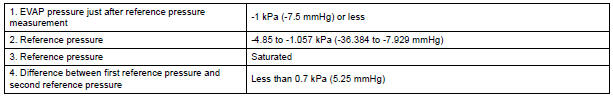
7. Leak check

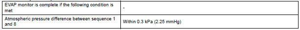
8. Atmospheric pressure measurement
TYPICAL MALFUNCTION THRESHOLDS

MONITOR RESULT
Refer to CHECKING MONITOR STATUS
 Oxygen (A/F) Sensor Pumping Current Circuit
DTC P2238 Oxygen (A/F) Sensor Pumping Current Circuit
Low (Bank 1 Sensor 1)
DTC P2239 Oxygen (A/F) Sensor Pumping Current Circuit
High (Bank 1 Sensor 1)
DTC P2241 Oxygen (A/F) Sensor Pumping Curre ...
 ECM / PCM Internal Engine Off Timer Performance
DTC P2610 ECM / PCM Internal Engine Off Timer Performance
DTC SUMMARY
DESCRIPTION
To ensure the accuracy of the EVAP (Evaporative Emission) monitor values, the
soak timer, which is built
int ...
Other materials:
Inspection
1. INSPECT ENGINE COOLANT TEMPERATURE SENSOR
Using an ohmmeter, measure the resistance
between the terminals.
Standard resistance
If the result is as specified, do not replace the
engine coolant temperature sensor.
If the result is not as specified, replace the
engine ...
Open in Side Squib LH Circuit
DTC B0116/48 Open in Side Squib LH Circuit
DESCRIPTION
The side squib LH circuit consists of the center airbag sensor assembly and
the front seat side assembly
LH.
This circuit instructs the SRS to deploy when deployment conditions are met.
DTC B0116/48 is recorded when an open circuit is ...
Auxiliary boxes
Type A
Push the lid.
Type B
Push down the knob.
Type C (if equipped)
Type D
Type E (if equipped)
Type F
Lift the lid.
Type G (if equipped)
Removing the second center seat.
Type H (if equipped)
Type I (if equip ...
