Toyota Sienna Service Manual: Engine
ON-VEHICLE INSPECTION
1. INSPECT ENGINE COOLANT
(a) Inspect the engine coolant (See page CO-1).
2. INSPECT ENGINE OIL
(a) Inspect the engine oil (See page LU-1).
3. INSPECT BATTERY
(a) Inspect the battery (See page CH-5).
4. INSPECT AIR CLEANER FILTER ELEMENT SUBASSEMBLY
(a) Remove the air cleaner filter element sub-assembly.
(b) Visually check that there is no dirt, blockage, and/or damage to the air cleaner filter element.
HINT:
- If there is any dirt or a blockage in the air cleaner filter element, clean it with compressed air
- If any dirt or a blockage remains even after cleaning the air cleaner filter element with compressed air, replace it.
5. INSPECT SPARK PLUG
(a) Inspect the spark plugs (See page IG-5).
6. INSPECT VALVE LASH ADJUSTER NOISE
(a) Rev up the engine several times. Check that the engine does not emit unusual noises.
If unusual noises occur, warm up the engine and idle it for over 30 minutes. Then repeat this procedure.
HINT:
If any defects or problems are found during the inspection above, perform lash adjuster inspection (See page EM-100).
7. INSPECT IGNITION TIMING
(a) Warm up the engine.
(b) When using the intelligent tester: Check the ignition timing.
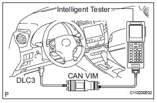
(1) Connect the intelligent tester to the DLC3.
(2) Enter DATA LIST mode with the intelligent tester.
Ignition timing: 8 to 12° BTDC at idle
HINT:
Refer to the intelligent tester operator's manual for help when selecting the DATA LIST.
(c) When not using the intelligent tester: Check the ignition timing.
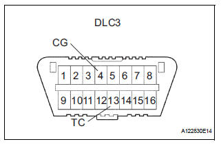
(1) Using SST, connect terminals 13 (TC) and 4 (CG) of the DLC3.
SST 09843-18040
NOTICE:
|
(2) Remove the V-bank cover.
(3) Pull out the red lead wire harness.
(4) Connect the tester terminal of the timing light to the red lead wire as shown in the illustration.
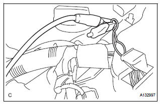
| NOTICE: Use a timing light which can detect the first signal. |
(5) Check the ignition timing at idle.
Ignition timing: 8 to 12° BTDC at idle
| NOTICE: When checking the ignition timing, the transmission should be in neutral. |
HINT:
Run the engine at 1000 to 1300 rpm for 5 seconds, and then check that the engine rpm returns to idle speed.
(6) Disconnect terminals 13 (TC) and 4 (CG) of the DLC3.
(7) Check the ignition timing at idle.
Ignition timing: 7 to 24° BTDC at idle
(8) Confirm that the ignition timing moves to the advanced angle side when the engine rpm is increased.
(9) Remove the timing light.
8. INSPECT ENGINE IDLE SPEED

(a) Warm up the engine.
(b) When using the intelligent tester: Check the idle speed.
(1) Connect the intelligent tester to the DLC3.
(2) Enter DATA LIST mode with the intelligent tester
Idle speed: 600 to 700 rpm
NOTICE:
|
HINT:
Refer to the intelligent tester operator's manual for further details.
(c) When not using the intelligent tester: Check the idle speed.
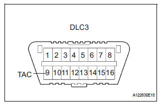
(1) Using SST, connect the tachometer test probe to terminal 9 (TAC) of the DLC3.
SST 09843-18030 (2) Check the idle speed.
Idle speed: 600 to 700 rpm
9. INSPECT COMPRESSION
(a) Warm up and stop the engine.
(b) Disconnect the injector connectors.
(c) Remove the intake air surge tank (See page ES- 521).
(d) Remove the 6 ignition coils.
(e) Remove the 6 spark plugs.
(f) Check the cylinder compression pressure.
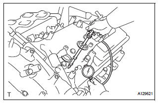
(1) Insert a compression gauge into the spark plug hole.
(2) While cranking the engine, measure the compression pressure.
Compression pressure: 1.3 MPa (13 kgf/cm2, 189 psi) Minimum pressure: 0.98 MPa (10 kgf/cm2, 142 psi) Difference between each cylinder: 0.1 MPa (1.0 kgf/cm2, 15 psi)
NOTICE:
|
(3) If the cylinder compression is low, pour a small amount of engine oil into the cylinder through the spark plug hole and inspect again.
HINT:
- If adding oil increases the compression, the piston rings and/or cylinder bore may be worn or damaged.
- If pressure stays low, a valve may be stuck or seated improperly, or there may be leakage in the gasket.
(g) Install the 6 spark plugs.
Torque: 18 N*m (184 kgf*cm, 13 ft.*lbf)
(h) Install the 6 ignition coils.
Torque: 10 N*m (102 kgf*cm, 7 ft.*lbf)
(i) Install the intake air surge tank (See page ES-522).
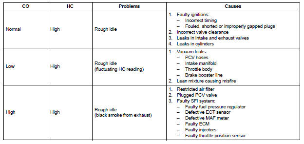
10. INSPECT CO/HC
(a) Start the engine.
(b) Run the engine at 2500 rpm for approximately 180 seconds.
(c) Insert the CO/HC meter testing probe at least 40 cm (1.3 ft.) into the tailpipe during idling.
(d) Check CO/HC concentration at idle and/or 2500 rpm.
HINT:
Check regulations and restrictions in your area when performing 2 mode CO/HC concentration testing (engine check at both idle speed and at 2500 rpm).
If the CO/HC concentration does not comply with regulations, perform troubleshooting in the order given below.
(1) Check air fuel ratio sensor and heated oxygen sensor operation.
(2) See the table below for possible causes, and then inspect and repair.
 Air fuel ratio sensor relay
INSPECTION
1. INSPECT AIR FUEL RATIO SENSOR RELAY
(a) Using an ohmmeter, measure the resistance
according to the value(s) in the table below.
Standard resistance
If the result is not as spe ...
 Drive belt
COMPONENTS
REMOVAL
1. REMOVE FRONT WHEEL RH
2. REMOVE FRONT FENDER APRON SEAL RH (See
page EM-26)
3. REMOVE V-RIBBED BELT
(a) Using SST, release the belt tension by turning the
belt tensi ...
Other materials:
Multiplex Communication Circuit
DESCRIPTION
INSPECTION PROCEDURE
1 GO TO CAN COMMUNICATION SYSTEM
(a) Refer to the CAN communication system (See page CA-
7).
(b) If the CAN communication system is operating normally,
proceed to the next step.
2 GO TO MULTIPLEX COMMUNICATION SYSTEM (BEAN)
(a) Refer to the multiplex com ...
Power window regulator
motor
INSPECTION
1. INSPECT POWER WINDOW REGULATOR MOTOR
(FRONT RH)
Remove the power window regulator motor.
Apply battery voltage to the motor connector
according to the table below.
NOTICE:
Do not apply battery to any terminals except
terminals 1 and 2.
Standard
2. INS ...
Diagnosis system
1. DESCRIPTION
(a) When troubleshooting OBD II vehicles, the only
difference from the usual troubleshooting procedure
is to connect an OBD II scan tool complying with
SAE J1987 or a intelligent tester to the vehicle, and
read off various data output from the vehicle's ECM.
(b) OBD II reg ...
