Toyota Sienna Service Manual: Fuel Receiver Gauge Malfunction
DESCRIPTION
The meter CPU uses the fuel sender gauge assembly to determine the level of the fuel in the fuel tank.
The resistance of the fuel sender gauge will vary between approximately 15 Ω with the float at the full position, and 410 Ω with the float at the empty position. The meter outputs battery voltage through two 820 Ω resistors that are mounted in parallel inside the meter ECU. The meter CPU measures the voltage between the variable resistor in the fuel sender gauge and the two resistors mounted in parallel in the meter. Voltage measured at this point will vary as the float of the fuel sender gauge is moved. The highest voltage observed should be approximately half of battery voltage.
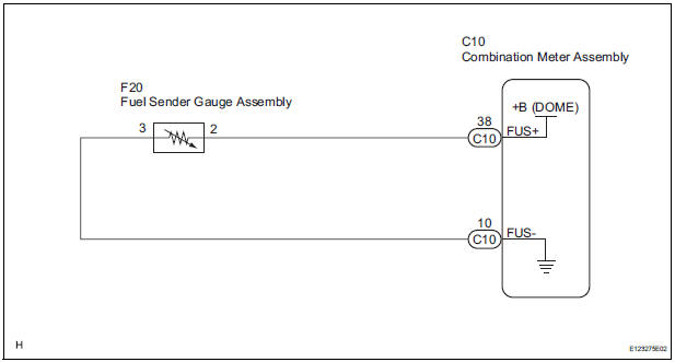
WIRING DIAGRAM
INSPECTION PROCEDURE
1 PERFORM ACTIVE TEST BY INTELLIGENT TESTER
- Connect the intelligent tester to the DLC3.
- Turn the ignition switch to the ON position.
- Turn the tester ON.
- Enter following menus: DIAGNOSIS / OBD/MOBD / METER / ACTIVE TEST.
- Check the operation by referring to the values in the table below.
METER:

OK: Needle indication is normal.
2 READ VALUE OF INTELLIGENT TESTER
- Connect the intelligent tester to the DLC3.
- Turn the ignition switch to the ON position.
- Turn the tester ON.
- Enter following menus: DIAGNOSIS / OBD/MOBD / METER / DATA LIST.
- Check the values by referring to the values in the table below
METER:
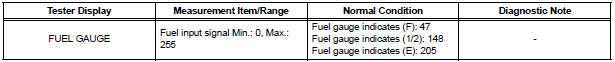
OK: Fuel value signal displayed on the tester is almost the same as needle indication
3 INSPECT FUEL SENDER GAUGE ASSEMBLY
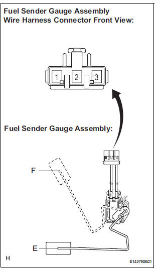
- Disconnect the connector from the fuel sender gauge.
- Check the the float moves smoothly between F and E.
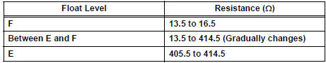
- Measure the resistance between terminals 1 and 2 of the connector according to the value(s) in the table below.
Standard resistance: Fuel sender gauge
4 CHECK HARNESS AND CONNECTOR (COMBINATION METER ASSEMBLY - FUEL SENDER GAUGE ASSEMBLY)
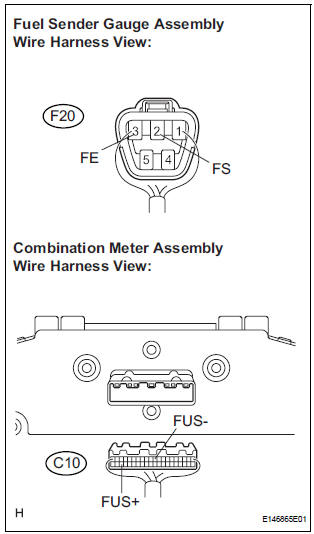
- Disconnect the F20 and C10 connectors.
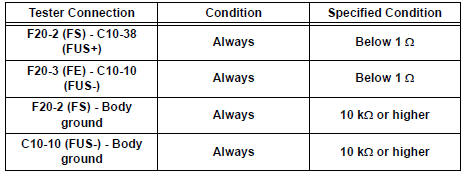
- Measure the resistance according to the value(s) in the table below.
Standard resistance
REPLACE COMBINATION METER ASSEMBLY
 Tachometer Malfunction
DESCRIPTION
The meter CPU receives the engine revolution signal from the ECM via the
direct lines. The meter CPU
displays engine revolution data that is calculated based on the data received
fro ...
 Engine Coolant Temperature Receiver Gauge Malfunction
DESCRIPTION
The meter CPU receives engine coolant temperature signals from the ECM via
the multiplex
communication lines. The meter CPU displays engine coolant temperature that is
calculated bas ...
Other materials:
Parts location
HOW TO PROCEED WITH
TROUBLESHOOTING
1 VEHICLE BROUGHT TO WORKSHOP
2 CUSTOMER PROBLEM ANALYSIS
(a) Confirm problem symptoms.
3 CHECK AND CLEAR DTCS
4 PROBLEM SYMPTOM CONFIRMATION
5 SYMPTOM SIMULATION
6 DTC CHECK (OTHER THAN MULTIPLEX DTC)
7 DTC CHART
8 PROBLEM SYMP ...
Problem symptoms table
Before inspecting the suspected areas listed in the table
below, check the fuse and relay.
Before inspecting the suspected areas listed in the table
below, check the DTCs.
Methods used to verify the cause of the problem are listed
in order of probability in the suspected are ...
CD cannot be Inserted / Played or CD is Ejected Right After Insertion
INSPECTION PROCEDURE
1 CHECK IF A PROPER CD IS INSERTED
Make sure that the CD is an audio CD or a CD with an
MP3 or WMA file, and that it is not deformed, flawed,
stained, burred, or otherwise defective.
OK:
Normal CD.
HINT:
Translucent or uniquely-shaped CDs cannot be
play ...
