Toyota Sienna Service Manual: Crankshaft position sensor
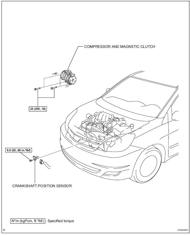
Components
Removal
1. Remove compressor and magnetic clutch
HINT: (See page AC-227 )
2. REMOVE CRANKSHAFT POSITION SENSOR
(a) Disconnect the crankshaft position sensor connector.
(b) Remove the bolt, and then remove the crankshaft position sensor.
INSPECTION
1. INSPECT CRANKSHAFT POSITION SENSOR
(a) Using an ohmmeter, measure the resistance between the terminals.
Standard resistance 
NOTICE:
|
If the resistance is not as specified, replace the crankshaft position sensor.
INSTALLATION
1. INSTALL CRANKSHAFT POSITION SENSOR
(a) Apply a light coat of engine oil to the O-ring on the crankshaft position sensor.
(b) Install the crankshaft position sensor with the bolt.
Torque: 9.0 N*m (92 kgf*cm, 80 in.*lbf) (c) Connect the crankshaft position sensor connector.
2. INSTALL COMPRESSOR AND MAGNETIC CLUTCH
HINT: (See page AC-231)
 Vvt sensor
COMPONENTS
ON-VEHICLE INSPECTION
1. CHECK VVT SENSOR OUTPUT VOLTAGE
(a) Turn the ignition switch to the ON position.
(b) Check the voltage between the specified terminal
and body grou ...
 Engine coolant temperature sensor
COMPONENTS
REMOVAL
1. DRAIN ENGINE COOLANT (See page CO-6)
2. REMOVE V-BANK COVER SUB-ASSEMBLY (See
page EM-28)
3. REMOVE NO. 2 AIR CLEANER INLET (See page EM-
28)
4. REMOVE NO. 1 AIR CLEAN ...
Other materials:
Throttle / Pedal Position Sensor / Switch "A/B"
Circuit
DTC P0120 Throttle / Pedal Position Sensor / Switch "A"
Circuit
DTC P0122 Throttle / Pedal Position Sensor / Switch "A"
Circuit Low Input
DTC P0123 Throttle / Pedal Position Sensor / Switch "A"
Circuit High Input
DTC P0220 Throttle / Pedal Position Sensor / Switch ...
Reassembly
1. INSTALL REAR DISC
(a) Aligning the matchmarks, install the rear disc.
HINT:
Select the installation position where the disc has
the minimum runout.
2. INSPECT DISC RUNOUT
(a) Temporarily fasten the disc with the hub nuts.
Torque: 103 N*m (1,050 kgf*cm, 76 ft.*lbf)
(b) Using a di ...
Inspection
1. Inspect pack clearance of reverse clutch
(A) install the intermediate shaft and needle roller
bearing onto the transaxle rear cover.
(B) using a dial indicator, measure the reverse clutch
pack clearance while applying and releasing
compressed air (392 kpa, 4.0 Kgf/cm2, 57 psi).
Pack c ...
