Toyota Sienna Service Manual: Engine front oil seal
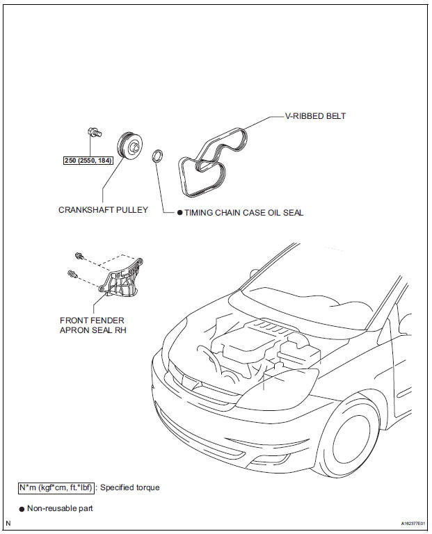
COMPONENTS
REMOVAL
1. REMOVE FRONT WHEEL RH 2. REMOVE FRONT FENDER APRON SEAL RH (See page EM-26) 3. REMOVE V-RIBBED BELT (See page EM-6) 4. REMOVE CRANKSHAFT PULLEY
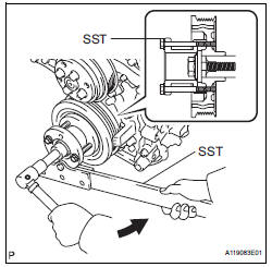
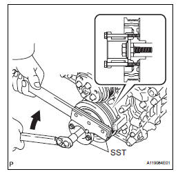
(a) Using SST, loosen the crankshaft pulley bolt.
SST 09213-70011 (09213-70020), 09330-00021
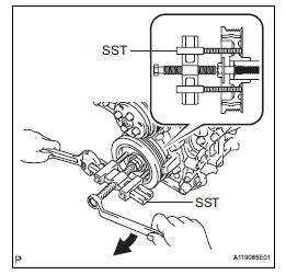
(b) Using SST, remove the crankshaft pulley bolt and crankshaft pulley.
SST 09950-50013 (09951-05010, 09952-05010, 09953-05020, 09954-05021)
5. REMOVE TIMING CHAIN CASE OIL SEAL
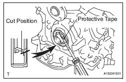
(a) Using a screwdriver, pry out the oil seal.
HINT:
Tape the screwdriver tip before use.
| NOTICE: After the removal, check the crankshaft for damage. If it is damaged, smooth the surface with 400-grit sandpaper. |
INSTALLATION
1. INSTALL TIMING CHAIN CASE OIL SEAL
(a) Apply MP grease to a new oil seal lip.
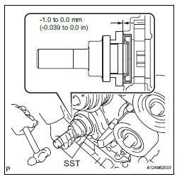
(b) Using SST and a hammer, tap in the oil seal until its surface is flush with the timing chain cover edge.
SST 09223-22010, 09506-35010
NOTICE:
|
2. INSTALL CRANKSHAFT PULLEY
(a) Align the pulley set key with the key groove of the pulley, and slide on the pulley.
(b) Using SST, install the pulley bolt.
SST 09213-70011 (09213-70020), 09330-00021 Torque: 250 N*m (2550 kgf*cm, 184 ft.*lbf)
3. INSTALL V-RIBBED BELT (See page EM-7) 4. INSTALL FRONT FENDER APRON SEAL RH (See page EM-62) 5. INSTALL FRONT WHEEL RH Torque: 103 N*m (1050 kgf*cm, 76 ft.*lbf)
 Drive belt
COMPONENTS
REMOVAL
1. REMOVE FRONT WHEEL RH
2. REMOVE FRONT FENDER APRON SEAL RH (See
page EM-26)
3. REMOVE V-RIBBED BELT
(a) Using SST, release the belt tension by turning the
belt tensi ...
 Engine rear oil seal
Components
Removal
1. REMOVE AUTOMATIC TRANSAXLE ASSEMBLY (for
2WD)
HINT:
See page AX-163.
2. REMOVE AUTOMATIC TRANSAXLE ASSEMBLY (for
4WD)
HINT:
See page AX-167.
3. REMOVE DRIVE PLATE A ...
Other materials:
Cranking Holding Function Circuit
DESCRIPTION
The system detects the ignition switch's starting signal (STSW) and then
supplies current to the starter
until the ECM judges that the engine has started successfully. The purpose is to
reduce the holding time
of the ignition key.
WIRING DIAGRAM
Refer to DTC P0617 (See page ...
On-vehicle inspection
1. CHECK POWER REAR NO. 2 SEAT with STOWING FUNCTION
Check the basic functions.
Operate the fold seat switch and power rear
No.2 seat switch and check to make sure each
seat function works:
Folding-down operation
Stowing operation
Return operation
...
Disassembly
1. REMOVE RETURN TUBE NO.2
(a) Using SST, remove the return tube No. 2.
SST 09023-12701
2. REMOVE STEERING LEFT TURN PRESSURE TUBE
(a) Using SST, remove the left turn pressure tube.
SST 09023-38201
(b) Remove the 2 O-rings from the left turn pressure
tube.
3. REMOVE STEERING RIGH ...
