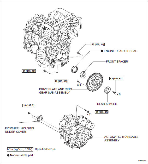
Toyota Sienna Service Manual: Engine rear oil seal
Components
Removal
1. REMOVE AUTOMATIC TRANSAXLE ASSEMBLY (for 2WD)
HINT:
See page AX-163.
2. REMOVE AUTOMATIC TRANSAXLE ASSEMBLY (for 4WD)
HINT: See page AX-167.
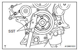
3. REMOVE DRIVE PLATE AND RING GEAR SUBASSEMBLY
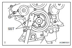
(a) Using SST, hold the crankshaft.
SST 09213-70011 (09213-70020), 09330-00021
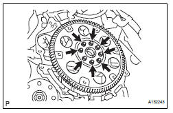
(b) Remove the 8 bolts, front spacer, drive plate and rear spacer.
4. REMOVE ENGINE REAR OIL SEAL
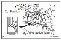
(a) Using a knife, cut off the oil seal lip.
(b) Using a screwdriver, pry out the oil seal.
NOTICE:
Be careful not to damage the crankshaft. Tape the screwdriver tip before use.
INSTALLATION
1. INSTALL ENGINE REAR OIL SEAL
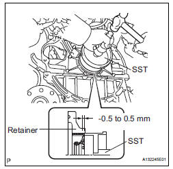
(a) Apply MP grease to a new oil seal lip.
(b) Using SST and a hammer, tap in the oil seal.
SST 09223-15030, 09950-70010 (09951-07150) Oil seal tap in depth: -0.5 to 0.5 mm (-0.020 to 0.020 in.)
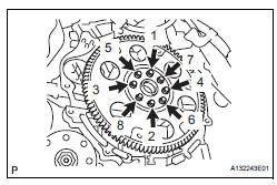
2. INSTALL DRIVE PLATE AND RING GEAR SUBASSEMBLY
(a) Using SST, hold the crankshaft.
SST 09213-70011 (09213-70020), 09330-00021
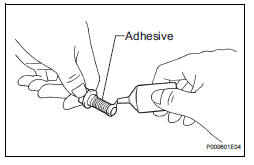
(b) Apply adhesive to 2 or 3 threads of the mounting bolt end.
Adhesive: Part No. 08833-00070, THREE BOND 1324 or equivalent
(1) Install the front spacer, drive plate and rear spacer on the crankshaft.
(2) Install and tighten the 8 mounting bolts uniformly in several steps.
Torque: 83 N*m (850 kgf*cm, 61 ft.*lbf)
3. INSTALL AUTOMATIC TRANSAXLE ASSEMBLY (for 2WD)
HINT:
See page AX-166.
4. INSTALL AUTOMATIC TRANSAXLE ASSEMBLY (for 4WD)
HINT:
See page AX-167.
 Engine front oil seal
COMPONENTS
REMOVAL
1. REMOVE FRONT WHEEL RH
2. REMOVE FRONT FENDER APRON SEAL RH (See
page EM-26)
3. REMOVE V-RIBBED BELT (See page EM-6)
4. REMOVE CRANKSHAFT PULLEY
(a) Using SST, loos ...
 Engine assembly
Components
REMOVAL
1. DISCHARGE FUEL SYSTEM PRESSURE (See page
FU-13)
2. DISCHARGE REFRIGERANT FROM
REFRIGERATION SYSTEM (See page AC-172)
3. REMO ...
Other materials:
Installation
1. Install transmission valve body assembly
(a) Install the shift solenoid valve SL1 to the valve body
assembly with the bolt.
Torque: 6.6 N*m (67 kgf*cm, 58 in.*lbf)
(b) Install the shift solenoid valve SL2 to the valve body
assembly with the bolt.
Torque: 11 N*m (110 kgf*cm, 8 ft ...
Tire pressure warning system
Your vehicle is equipped with a tire pressure warning system that uses
tire pressure warning valves and transmitters to detect low tire inflation
pressure before serious problems arise.
Vehicles with compact spare tire: The compact spare tire is not
equipped with the tire pressure warning valve ...
Power Slide Door Warning Buzzer RH does not Sound
DESCRIPTION
The power slide door system uses warning buzzers built into RH
slide doors respectively. Each buzzer
has 2 ways of sounding that are used differently according to the
situations:
When all the following conditions are met, the warning buzzer sounds at
a cycle of ...
