Toyota Sienna Service Manual: Fold Seat Switch Circuit
DESCRIPTION
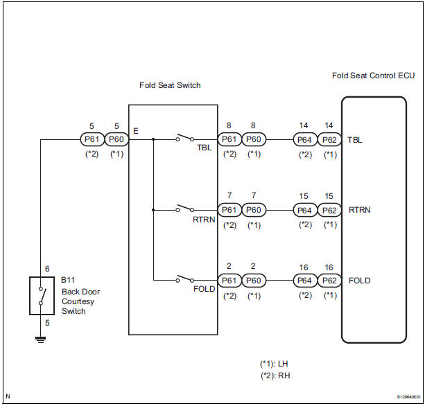
When the fold seat switch is operated, a switch operation signal is sent to the fold seat control ECU. The ECU receives switch operation signals from each switch and activates the folding motor, reclining motor, and release actuator.
WIRING DIAGRAM
INSPECTION PROCEDURE
1 INSPECT FOLD SEAT CONTROL ECU
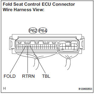
- Remove the fold seat control ECU with connectors still connected.
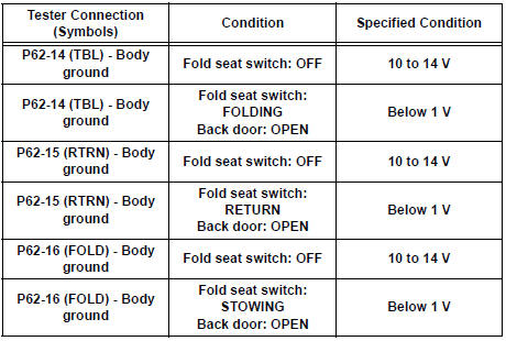
- Measure the voltage according to the value(s) in the table below.
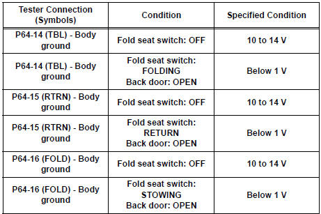
Standard voltage: LH side
RH side
2 INSPECT FOLD SEAT SWITCH
- Remove the fold seat switch.
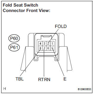
- Disconnect the connector from the fold seat switch.
- Measure the resistance according to the value(s) in the table below.
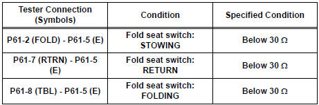
Standard resistance: LH side
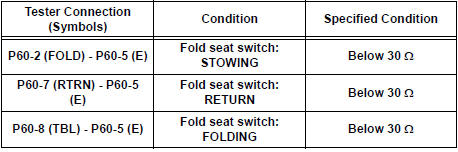
RH side
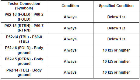
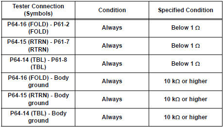
3 CHECK HARNESS AND CONNECTOR (FOLD SEAT SWITCH - FOLD SEAT CONTROL ECU)
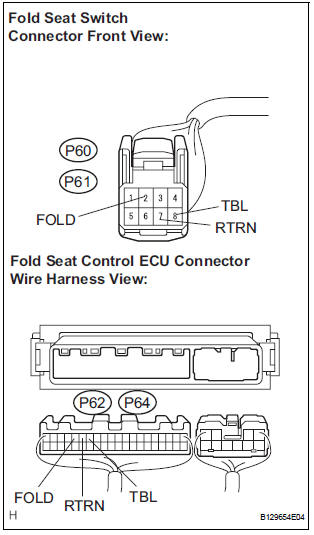
- Disconnect the connector from the fold seat control ECU.
- Measure the resistance according to the value(s) in the table below.
Standard resistance: LH side
RH side
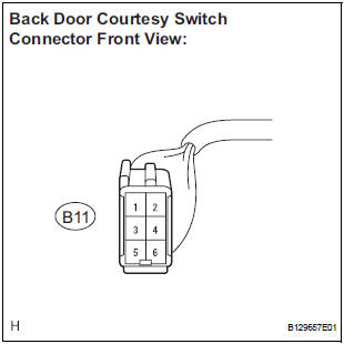
4 CHECK HARNESS AND CONNECTOR (BACK DOOR COURTESY SWITCH - FOLD SEAT SWITCH)
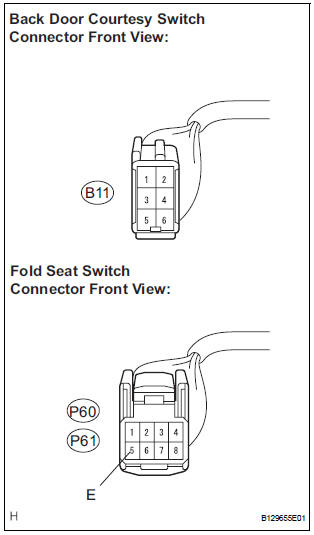
- Disconnect the connector from the back door courtesy switch.
- Measure the resistance according to the value(s) in the table below.
Standard resistance: LH side
RH side
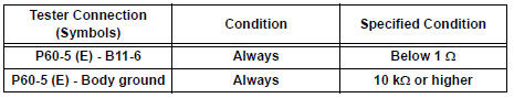
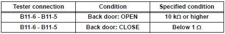
5 INSPECT BACK DOOR COURTESY SWITCH
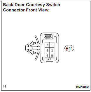
- Measure the resistance according to the value(s) in the table below.
Standard resistance
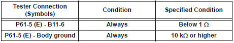
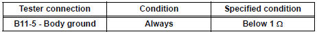
6 CHECK HARNESS AND CONNECTOR (BACK DOOR COURTESY SWITCH - BODY GROUND)
- Measure the resistance according to the value(s) in the table below.
Standard resistance
REPLACE FOLD SEAT CONTROL ECU
 Power Source Circuit
DESCRIPTION
Power is supplied to the fold seat control ECU through the L-RR2 SEAT and
R-RR2 SEAT fuses.
WIRING DIAGRAM
INSPECTION PROCEDURE
1 INSPECT FUSE (L-RR2 SEAT, R-RR2 SEAT)
Re ...
 Folding Motor Circuit
DESCRIPTION
The fold seat control ECU receives a switch operation signal from the fold
seat switch and activates the
folding motor. At this time, the Hall IC (seat cushion position sensor) detects ...
Other materials:
Open in Curtain Shield Squib LH Circuit
DTC B1166/88 Open in Curtain Shield Squib LH Circuit
DESCRIPTION
The curtain shield squib LH circuit consists of the center airbag sensor
assembly and the curtain shield
airbag assembly LH.
The circuit instructs the SRS to deploy when deployment conditions are met.
DTC B1166/88 is recorde ...
Installing the second seats
Installing the second outside seats
Align the marking on the seat side cover to the marking on the
rail cover and align the marking on the seat front/back cover to
the rail.
Tip-up seat
Ottoman seat
Lower the seat and engage the latches.
If you locked the seat lat ...
Safety information
for children
Observe the following precautions when children are in the vehicle.
Use a child restraint system appropriate for the child, until the
child becomes large enough to properly wear the vehicle’s seat
belt.
It is recommended that children sit in the rear seats to avoid
accidental
contact ...
