Toyota Sienna Service Manual: Power Source Circuit
DESCRIPTION
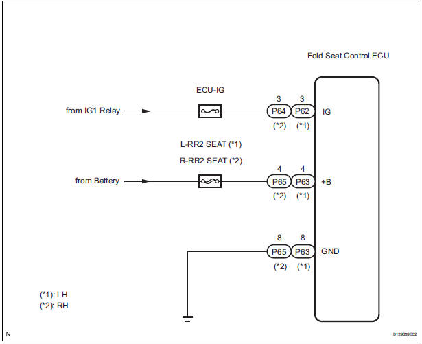
Power is supplied to the fold seat control ECU through the L-RR2 SEAT and R-RR2 SEAT fuses.
WIRING DIAGRAM
INSPECTION PROCEDURE
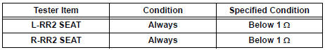
1 INSPECT FUSE (L-RR2 SEAT, R-RR2 SEAT)
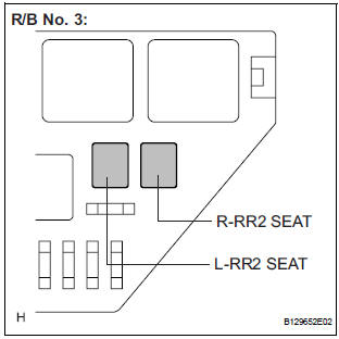
- Remove the fuses from the R/B No. 3.
- Measure the resistance according to the value(s) in the table below.
Standard resistance
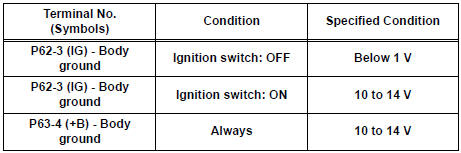
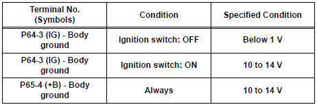
2 CHECK HARNESS AND CONNECTOR (POWER SOURCE)
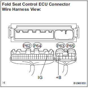
- Remove the fold seat control ECU.
- Disconnect the connectors from the fold seat control ECU.
- Measure the voltage according to the value(s) in the table below.
Standard voltage: LH side
RH side
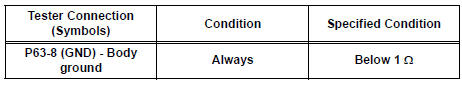
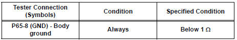
3 CHECK HARNESS AND CONNECTOR (GROUND)
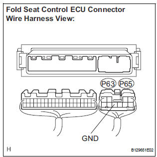
- Measure the resistance according to the value(s) in the table below.
Standard resistance: LH side
RH side
PROCEED TO NEXT CIRCUIT INSPECTION SHOWN IN PROBLEM SYMPTOMS TABLE
 Indicator Circuit
DESCRIPTION
This system has two indicator lights. One of the indicator lights is built
into the fold seat switch. This
indicator light receives power from the fold seat control ECU. It comes on or ...
 Fold Seat Switch Circuit
DESCRIPTION
When the fold seat switch is operated, a switch operation signal is sent to
the fold seat control ECU. The
ECU receives switch operation signals from each switch and activates the fold ...
Other materials:
Front Occupant Classification Sensor LH Circuit
Malfunction
DTC B1780 Front Occupant Classification Sensor LH Circuit
Malfunction
DESCRIPTION
The front occupant classification sensor LH circuit consists of the occupant
classification ECU and the
front occupant classification sensor LH.
DTC B1780 is recorded when a malfunction is detected in the fron ...
Heater relay (for rear air conditioning system)
ON-VEHICLE INSPECTION
1. INSPECT REAR HEATER RELAY
(a) Remove the rear heater relay.
(b) Measure the resistance according to the value(s) in
the table below.
Standard resistance
If the resistance is not as specified, replace the rear
heater relay. ...
Installation
1. Install torque converter clutch assembly
(a) Install the torque converter clutch to the automatic
transaxle.
(b) Using vernier calipers and a straight edge, measure
the dimension "A" between the transaxle fitting part
of the engine and the converter fitting part of the
drive ...
