Toyota Sienna Service Manual: Freeze frame data
1. DESCRIPTION
(a) The ECM records vehicle and driving condition information as freeze frame data the moment a DTC is stored. When troubleshooting, freeze frame data can be helpful in determining whether the vehicle was running or stopped, whether the engine was warmed up or not, whether the air-fuel ratio was lean or rich, as well as other data recorded at the time of a malfunction.
HINT:
If it is impossible to duplicate the problem even though a DTC is detected, confirm the freeze frame data.
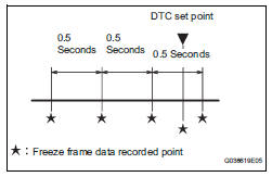
(b) The ECM records engine conditions in the form of freeze frame data every 0.5 seconds. Using the intelligent tester, five separate sets of freeze frame data, including the data values at the time when the DTC was set, can be checked.
- 3 data sets before the DTC was set
- 1 data set when the DTC was set
- 1 data set after the DTC was set
These data sets can be used to simulate the condition of the vehicle around the time of the occurrence of the malfunction. The data may assist in identifying of the cause of the malfunction, and in judging whether it was temporary or not.
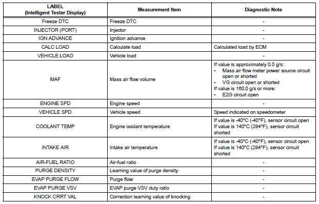
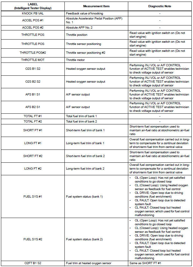
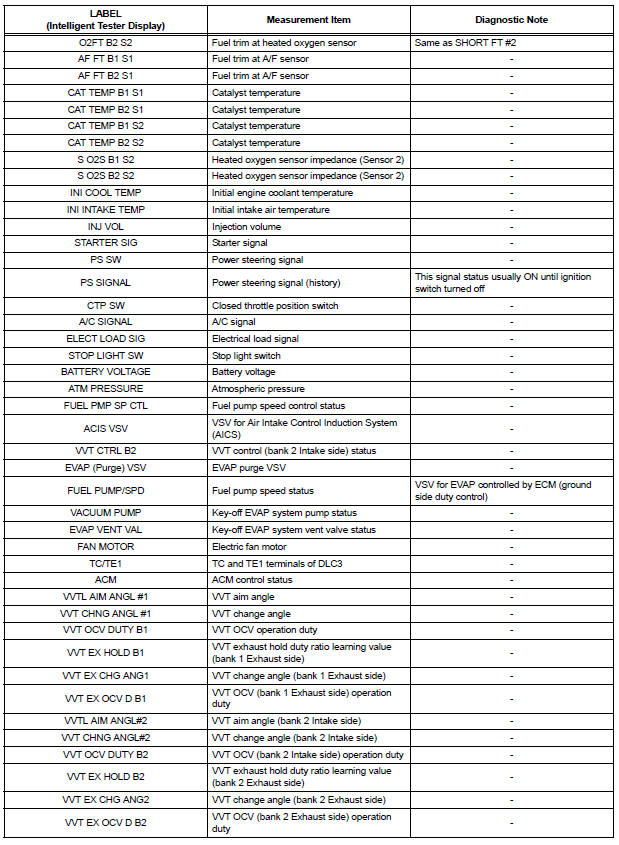
2. LIST OF FREEZE FRAME DATA
 Dtc check / clear
Notice:All the stored dtcs and freeze frame data are
erased if:
1) the ecm is changed from normal mode to check mode
or vice versa; or 2) the ignition switch is turned from on
to a ...
 Check mode procedure
HINT:
Intelligent tester only:
Compared to normal mode, check mode is more sensitive to
malfunctions. Therefore, check mode can detect the
malfunctions that cannot be detected by normal mode.
...
Other materials:
ACIS Control Circuit
DESCRIPTION
This circuit opens and closes the Intake Air Control Valve (IACV) in response
to changes in the engine
load in order to increase the intake efficiency (ACIS: Acoustic Control
Induction System).
When the engine speed is between 0 and 4450 rpm and the throttle valve opening
angl ...
Installation
1. INSTALL CIGARETTE LIGHTER ASSEMBLY
Engage the 2 claws to install the cigarette lighter
assembly.
Install the cigarette lighter knob.
2. INSTALL CIGARETTE LIGHTER COVER
Engage the 2 claws to install the cigarette lighter
cover.
3. INSTALL INSTRUMENT CL ...
Radio Broadcast cannot be Received or Poor Reception
INSPECTION PROCEDURE
1 CHECK RADIO AND NAVIGATION ASSEMBLY
Check the radio's automatic station search function.
Check the radio's automatic station search function
by activating it.
OK:
The radio's automatic station search function
works properly.
2 INSPECT RADIO AND NAVIGATION AS ...
