Toyota Sienna Service Manual: Tachometer Malfunction
DESCRIPTION
The meter CPU receives the engine revolution signal from the ECM via the direct lines. The meter CPU displays engine revolution data that is calculated based on the data received from the ECM.
WIRING DIAGRAM
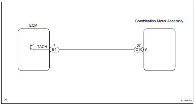
INSPECTION PROCEDURE
1 PERFORM ACTIVE TEST BY INTELLIGENT TESTER
- Connect the intelligent tester to the DLC3.
- Turn the switch to the ON position.
- Turn the tester ON.
- Enter the following menus: DIAGNOSIS / OBD/MOBD / METER / ACTIVE TEST.
- Check the operation by referring to the values in the table below.
METER:

OK: Needle indication is normal.
2 READ VALUE OF INTELLIGENT TESTER (ENGINE SPEED SIGNAL)
- Connect the intelligent tester to the DLC3.
- Turn the switch to the ON position.
- Turn the tester ON.
- Enter the following menus: DIAGNOSIS / OBD/MOBD / METER / DATA LIST.
- Check the values by referring to the values in the table below
METER:

OK: Engine speed displayed on the tester is almost the same as the actual engine speed.
REPLACE COMBINATION METER ASSEMBLY
3 READ VALUE OF INTELLIGENT TESTER (ENGINE SPEED SIGNAL)
- Connect the intelligent tester to the DLC3.
- Turn the switch to the ON position.
- Turn the tester ON.
- Enter the following menus: DIAGNOSIS / OBD/MOBD / ENGINE / ACTIVE TEST.
- Check the values by referring to the values in the table below.
ENGINE:

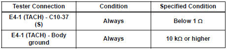
4 CHECK HARNESS AND CONNECTOR (COMBINATION METER - ECM)
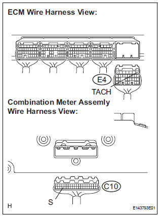
- Disconnect the E4 and C10 connectors.
- Measure the resistance according to the value(s) in the table below.
Standard resistance
5 INSPECT COMBINATION METER ASSEMBLY
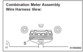
- Check the input signal waveform.
- Remove the combination meter with the connector still connected.
- Connect the oscilloscope to terminal C10-37 (S) and body ground.
- Start the engine.
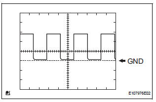
- Check the signal waveform according to the condition(s) in the table below.
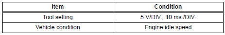
OK: The waveform is displayed as shown in the illustration
REPLACE ECM
 Speedometer Malfunction
DESCRIPTION
Factors that affect the indicated vehicle speed include tire size, tire
inflation, and tire wear. The speed indicated on the speedometer has an
allowable margin of error. This can be ...
 Fuel Receiver Gauge Malfunction
DESCRIPTION
The meter CPU uses the fuel sender gauge assembly to determine the level of
the fuel in the fuel tank.
The resistance of the fuel sender gauge will vary between approximately 15 ] ...
Other materials:
Short to B+ in Rear Curtain Shield Squib LH
Circuit
DTC B1638/86 Short to B+ in Rear Curtain Shield Squib LH
Circuit
DESCRIPTION
The rear curtain shield squib LH circuit consists of the center airbag sensor
assembly and the curtain
shield airbag assembly LH.
The circuit instructs the SRS to deploy when deployment conditions are met.
DTC B ...
Removal
HINT:
On the RH side, use the same procedures as on the LH side.
1. REMOVE SLIDE DOOR
Remove the rear door scuff plate (See page IR-7).
Remove the back door scuff plate (See page ED-
214).
Remove the quarter trim panel (See page IR-9).
Remove the upper rail cushion from the rail up ...
Adjustment
HINT:
On the RH side, use the same procedures as on the LH
side.
Since a centering bolt is used as door hinge mounting
bolts on the body side and the door side, the door cannot
be adjusted with them on. Substitute a bolt with a washer
for the centering bolt.
1. INSPECT BACK DOOR PAN ...
