Toyota Sienna Service Manual: Hydraulic test
1. Perform hydraulic test
(a) Measure the line pressure.
NOTICE:
|
(1) Warm up the ATF (Automatic Transmission Fluid).
(2) Lift the vehicle up.
(3) Remove the engine under cover.
(4) Connect the intelligent tester together with the CAN VIM (controller area network vehicle interface module) to the DLC3.
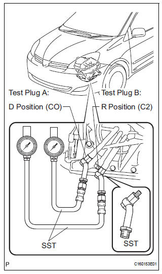
(5) Remove the test plug A on the transaxle case front left side and install the SST.
SST 09992-00095 (09992-00231, 09992- 00271)
| NOTICE: There is a difference in installation point between D position and R position. |
(6) Start the engine.
(7) Using intelligent tester, shift to D position and hold 3rd gear by active test, and measure the line pressure in idling.
Specified line pressure:

(8) Turn the ignition switch off.
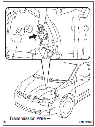
(9) Disconnect the connector of the transmission wire.
HINT: Disconnect the connector only when performing the D position stall test.
(10)Start the engine.
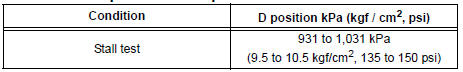
(11)Firmly depress the brake pedal, shift to the D position, depress the accelerator pedal all the way down and check the line pressure while the stall test is performed.
Specified line pressure:
(12)Turn the ignition switch off.
(13)Remove the SST, install the test plug A.
(14)Remove the test plug B, install the SST and start engine.
SST 09992-00095 (09992-00231, 09992- 00271)
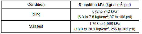
(15)Connect the transmission wire connector, depress the brake pedal firmly, shift to the R position and check that the line pressure while the engine is idling and during the stall test.
Specified line pressure:
(16)Remove the SST, install the test plug B.
(17)Clear the DTC.
Evaluation:
| Problem | Possible cause |
| Measured values are higher than specified in all positions |
|
| Measured values are lower than specified in all positions |
|
| Pressure is low in the D position only |
|
| Pressure is low in the R position only |
|
 Mechanical system tests
1. PERFORM MECHANICAL SYSTEM TESTS
(a) Measure the stall speed.
The object of this test is to check the overall
performance of the transaxle and engine by
measuring the stall speeds in the D pos ...
 Manual shifting test
1. Perform manual shifting test
Hint:
With this test, it can be determined whether the
trouble occurs in the electrical circuit or is a
mechanical problem in the transaxle.
If any abnormali ...
Other materials:
Terminals of ECU
1. CHECK INSTRUMENT PANEL J/B ASSEMBLY
(MULTIPLEX NETWORK BODY ECU)
Disconnect the B6, B7 and B9 ECU connectors.
Disconnect the 1A, 1C, 1L and 1K J/B connectors.
Measure the voltage and resistance between each
terminal of the wire harness side connectors and
body gro ...
Registration Complete Indication Error/ Registration Demand Transmission/
Multiple Frame Incomplete
DTC 01-E0 Registration Complete Indication Error
DTC 01-E3 Registration Demand Transmission
DTC 01-E4 Multiple Frame Incomplete
DESCRIPTION
DTC No.
DTC Detection Condition
Trouble Area
01-E0
"Registration complete" signal from the master device
c ...
Indicator Circuit
DESCRIPTION
This system has two indicator lights. One of the indicator lights is built
into the fold seat switch. This
indicator light receives power from the fold seat control ECU. It comes on or
blinks when the system
detects that an object is caught or when the seat operation conditions ar ...
