Toyota Sienna Service Manual: IG Power Source Circuit
DESCRIPTION
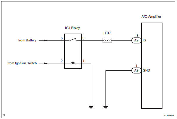
The main power source is supplied to the A/C amplifier when the ignition switch is turned to the ON position.
The power source is used for operating the A/C amplifier and servo motor, etc.
WIRING DIAGRAM
INSPECTION PROCEDURE
HINT: Start the engine before inspection. Check the IG1 relay or battery if the engine does not start.
1 INSPECT FUSE (HTR)
(a) Remove the HTR fuse from the driver side junction block.
(b) Measure the resistance according to the value(s) in the table below.
Standard resistance 


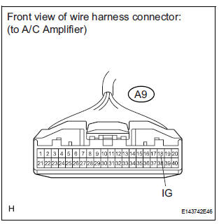
2 INSPECT A/C AMPLIFIER (IG - GND)
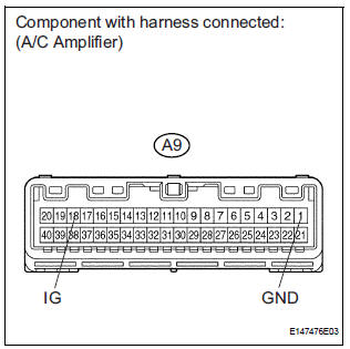
(a) Remove the A/C amplifier with its connectors still connected.
(b) Turn the ignition switch to the ON position.
(c) Measure the voltage according to the value(s) in the table below.
Standard voltage 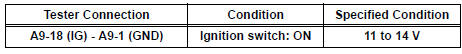


PROCEED TO NEXT CIRCUIT INSPECTION SHOWN IN PROBLEM SYMPTOMS TABLE
3 CHECK HARNESS AND CONNECTOR (A/C AMPLIFIER - BATTERY)
(a) Disconnect the connector from the A/C amplifier.
(b) Measure the voltage according to the value(s) in the table below.
Standard voltage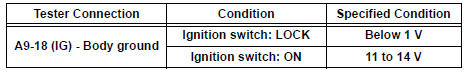

4 CHECK HARNESS AND CONNECTOR (A/C AMPLIFIER - BODY GROUND)
(a) Measure the resistance according to the value(s) in the table below.
Standard resistance 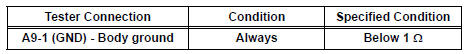

REPLACE A/C AMPLIFIER
 Rear Blower Motor Circuit
DESCRIPTION
Power to the rear blower motor is supplied from the battery via the RR A/C
relay.
The rear blower motor speed level varies between 0 and 31 based on the voltage
difference measured ...
 ACC Power Source Circuit
DESCRIPTION
This circuit supplies power to the A/C amplifier and the illumination for the
clock.
WIRING DIAGRAM
INSPECTION PROCEDURE
1 INSPECT FUSE (ECU ACC)
(a) Remove the ECU ACC fuse fr ...
Other materials:
Short in Rear Curtain Shield Squib RH Circuit
DTC B1630/83 Short in Rear Curtain Shield Squib RH Circuit
DESCRIPTION
The rear curtain shield squib RH circuit consists of the center airbag sensor
assembly and the curtain
shield airbag assembly RH.
The circuit instructs the SRS to deploy when deployment conditions are met.
DTC B1630/83 ...
Replacement
1. DISCHARGE REFRIGERANT FROM
REFRIGERATION SYSTEM
SST 07110-58060 (07117-58080, 07117-58090,
07117-78050, 07117-88060, 07117-88070,
07117-88080)
(a) Turn the A/C switch to ON.
(b) Operating the cooler compressor at the engine rpm
of approx. 1,000 for 5 to 6 minutes, circulate the
refriger ...
System description
1. GENERAL
This system uses ultrasonic sensors to detect any
obstacles at the corners and the rear of the vehicle.
The system then informs the driver of the distance
between the sensors and the obstacles as well as
their positions by indicating them on the clearance
sonar displ ...
