Toyota Sienna Service Manual: Internal Control Module Random Access Memory (RAM) Error

DESCRIPTION
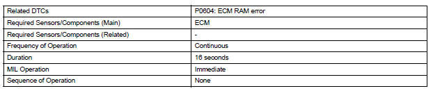
The ECM continuously monitors its own internal memory status, internal circuits, and output signals transmitted to the throttle actuator. This self-check ensures that the ECM is functioning properly. If any malfunction is detected, the ECM sets the appropriate DTC and illuminates the MIL.
The ECM memory status is diagnosed by internal mirroring of the main CPU and the sub CPU to detect Random Access Memory (RAM) errors. The two CPUs also perform continuous mutual monitoring. The ECM illuminates the MIL and sets a DTC if: 1) outputs from the two CPUs are different or deviate from the standards, 2) the signals sent to the throttle actuator deviate from the standards, 3) a malfunction is found in the throttle actuator supply voltage, and 4) any other ECM malfunction is found.

MONITOR STRATEGY
TYPICAL ENABLING CONDITIONS

TYPICAL MALFUNCTION THRESHOLDS

INSPECTION PROCEDURE
Read freeze frame data using the intelligent tester. Freeze frame data records the engine condition when malfunctions are detected. When troubleshooting, freeze frame data can help determine if the vehicle was moving or stationary, if the engine was warmed up or not, if the air-fuel ratio was lean or rich, and other data from the time the malfunction occurred.
1 CHECK ANY OTHER DTCS OUTPUT (IN ADDITION TO DTC P0604)
(a) Connect the intelligent tester to the DLC3.
(b) Turn the ignition switch to the ON position.
(c) Turn the tester on.
(d) Select the following menu items: DIAGNOSIS / ENHANCED OBD II / DTC INFO / CURRENT CODES.
(e) Read DTCs.
Result 


REPLACE ECM
 System Voltage
MONITOR DESCRIPTION
The battery supplies electricity to the ECM even when the ignition switch is
off. This power allows the
ECM to store data such as DTC history, freeze frame data and fuel tr ...
 ECM / PCM Processor
DESCRIPTION
The ECM continuously monitors its internal processors (CPUs), A/F sensor
transistors and heated oxygen
sensor (HO2S) transistors. This self-check ensures that the ECM is functionin ...
Other materials:
Shift Solenoid "D" Performance (Shift Solenoid
Valve S4)
SYSTEM DESCRIPTION
The ECM uses signals from the vehicle speed sensor to detect the actual gear
position (1st, 2nd, 3rd, 4th
or 5th gear).
Then the ECM compares the actual gear with the shift schedule in the ECM memory
to detect mechanical
problems of the shift solenoid valves, valve b ...
Panel Switches do not Function
INSPECTION PROCEDURE
1 CHECK PANEL SWITCH
Check for foreign matter around the switches that might
prevent operation.
OK:
No foreign matter is found
2 CHECK PANEL SWITCH (DISPLAY CHECK MODE)
Enter the "Display Check" mode (Panel Switch Check).
Operate the abnorma ...
Customize parameters
HINT:
The following items can be customized.
NOTICE:
When the customer requests a change in a function,
first make sure that customization of the function(s) is
possible.
Be sure to record the current settings before
customizing.
When troubleshooting a function, fir ...
