Toyota Sienna Service Manual: Adjustment
HINT: If the malfunction does not disappear by following the procedure in ADJUSTMENT and the rear No. 2 seat assembly needs to be replaced, do not disassemble the rear No. 2 seat assembly.
1. ADJUST FRONT LEG
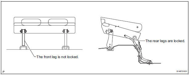
HINT: Perform the following procedure if the inner leg does not lock.
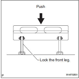
- Push down on the rear No. 2 seat assembly to lock the front leg.
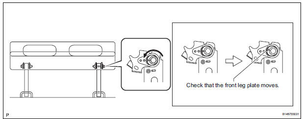
- Loosen the bolt on the front leg that has locked and move the rear No. 2 seat assembly up and down a few times.
NOTICE: Check that the front leg plate moves.
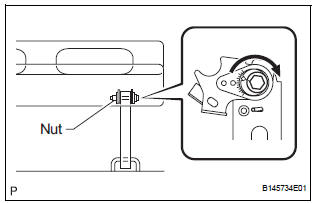
- Tighten the bolt.
Torque: 14.5 N*m (153 kgf*cm, 11 ft.*lbf) NOTICE: Hold the nut to prevent it from turning.
- Check that the rear No. 2 seat assembly operates
normally and both front legs lock securely.
NOTICE: If any of the front legs do not lock, loosen the bolt on the front leg that has not locked, and perform the procedure from (b) again.
2. REINSTALL REAR NO. 2 SEAT ASSEMBLY
HINT: Perform the following procedure if the rear No. 2 seat assembly is removed with any of the 4 legs released or if the rear legs are moved with the rear No. 2 seat assembly removed.
- Remove the following components:
- Rear No. 2 seat leg side garnish sub-assembly
- Rear seat leg garnish sub-assembly
- No. 2 seat hinge cover
- Rear No. 2 seat assembly
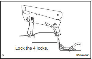
- Lock the rear legs to the striker.
- Lock the front legs to the striker.
- If any of the front legs do not lock, perform the following procedure:
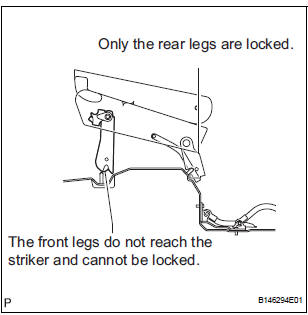
- Connect the connector.

- Operate the stowing/return switch to set the rear legs to the most upright position.
- Lock the front legs to the striker.
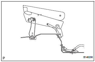
- Align the links of the No. 2 seat leg sub-assembly with the No. 2 seat cushion frame sub-assembly.
- Align the screw holes on the No. 2 cushion frame
sub-assembly with the square link holes on the No.
2 seat leg sub-assembly.
HINT: If the holes do not align, move the No. 2 seat cushion frame sub-assembly horizontally to align the holes.
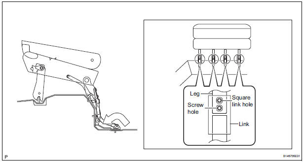
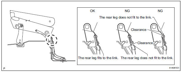
- Operate the stowing/return switch to adjust the rear legs so that the rear legs fit to the links of the No. 2 seat leg sub-assembly as shown in the illustration.
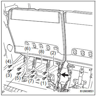
- Install the 8 bolts.
Torque: 19 N*m (194 kgf*cm, 14 ft.*lbf) NOTICE: Tighten the bolts in the order shown in the illustration.
- Install the following components:
- No. 2 seat hinge cover
- Rear seat leg garnish sub-assembly
- Rear No. 2 seat leg side garnish sub-assembly
- Check that the rear No. 2 seat assembly operates normally and the rear legs lock securely.
NOTICE: If any of the front legs do not lock normally, perform the procedure in "1. ADJUST FRONT LEG".
 Disassembly
1. REMOVE REAR NO. 2 SEAT COVER BEZEL
Remove the 5 screws.
Disengage the 5 claws and remove the rear No. 2
seat cover bezel.
2. REMOVE REAR SEAT RECLINING COVER LH
& ...
 Reassembly
1. INSTALL NO. 2 SEAT LEG SUB-ASSEMBLY
Install the No. 2 seat leg sub-assembly with the 3
bolts and 2 nuts.
Torque: 19 N*m (194 kgf*cm, 14 ft.*lbf)
NOTICE:
Tighten the bolts and ...
Other materials:
Diagnosis system
1. CHECK DLC3
(a) The vehicle's ECM uses the ISO 15765-4 for
communication. The terminal arrangement of the
DLC3 complies with SAE J1962 and matches the
ISO 15765-4 format.
HINT:
Connect the cable of the intelligent tester to the
DLC3, turn the ignition switch to the ON position
and atte ...
Typical DOT and Tire Identification Number (TIN)
DOT symbol*
Tire Identification Number (TIN)
Tire manufacturer’s identification
mark
Tire size code
Manufacturer’s optional tire
type code (3 or 4 letters)
Manufacturing week
Manufacturing year
*: The DOT symbol certifies that the tire conforms to applicable Federal
Mo ...
Engine Immobiliser System Malfunction
DTC B2799 Engine Immobiliser System Malfunction
DESCRIPTION
This DTC is output when the ECM detects errors in communication between the
transponder key ECU
and the ECM, or in the communication lines. This DTC is also output when an
engine start is attempted
while the ECU communication ID bet ...
