Toyota Sienna Service Manual: Inspection
1. INSPECT FUEL INJECTOR ASSEMBLYV
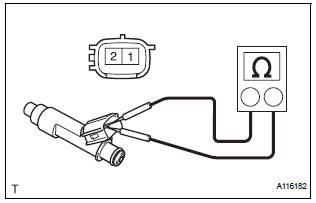
(A) inspect the injector resistance.
(1) Using an ohmmeter, measure the resistance between the terminals.
Standard resistance
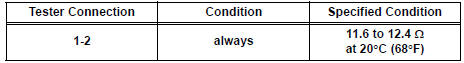
If the resistance is not as specified, replace the injector.
(b) Inspect the injection volume.
| CAUTION:
This test involves high-pressure fuel and
electricity. Take every precaution regarding the
safe handling of both fuel and electricity.
Perform this test in a safe area, and avoid any sparks or flames. Do not smoke. |
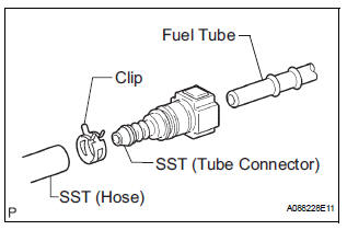
(1) Install the fuel tube connector to SST (hose), then connect the tube connector to the fuel pipe (vehicle side).
SST 09268-31011 (09268-41500, 90467- 13001, 95336-08070)
(2) Install the O-ring to the fuel injector subassembly.
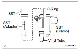
(3) Connect SST (adaptor and hose) to the injector, and hold the injector and union with SST (clamp).
SST 09268-31011 (90467-13001, 95336- 08070), 09268-41140, 09268-41400
(4) Put the injector into the graduated cylinder.
| CAUTION: Install a suitable vinyl tube onto the injector to contain gasoline spray. |
(5) Operate the fuel pump (See page FU-7).
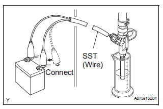
(6) Connect SST (wire) to the injector and the battery for 15 seconds, and measure the injection volume with the graduated cylinder.
Test each injector 2 or 3 times.
SST 09842-30080
Volume: 84 to 100 cm3 (5.1 to 6.0 cu in.) in 15 seconds
Difference between each injector: 16 cm3 (0.98 cu in.) or less
If the injection volume is not as specified, replace the injector.
(c) Check for leakage.
(1) In the condition above, disconnect the tester probes of SST (wire) from the battery and check for fuel leakage from the injector.
Fuel drop: 1 drop or less in 16 minutes
 Removal
1. DISCHARGE FUEL SYSTEM PRESSURE
HINT:
See page FU-1.
2. DISCONNECT CABLE FROM NEGATIVE BATTERY
TERMINAL
3. REMOVE NO. 1 ENGINE UNDER COVER
4. DRAIN ENGINE COOLANT (See page CO-6)
5. REMOVE FR ...
 Installation
1. INSTALL FUEL INJECTOR ASSEMBLY
(a) Apply a light coat of spindle oil or gasoline to new Orings,
and install them to each injector.
(b) Apply a light coat of spindle oil or gasoline where ...
Other materials:
Input instructions
(a) The general VIN input instructions using the
intelligent tester are shown below:
(b) The arrow buttons (UP, DOWN, RIGHT and LEFT)
and numerical buttons (0 to 9) are used to input the
VIN.
(c) Cursor Operation
To move the cursor around the tester screen, press
the RIGHT and LEFT buttons. ...
Installation
1. INSTALL STABILIZER BAR FRONT
2. INSTALL FRONT STABILIZER BAR BUSH NO.1
(a) Install the front stabilizer bar bush No. 1.
HINT:
Install the bushing to the outer side of the bushing
stopper on the stabilizer bar as shown in the
illustration.
4. INSTALL RACK & PINION POWER STEERING GEA ...
Customizable features
Settings that can be changed using the audio system screen
Settings that can be changed using the multi-information display
Settings that can be changed by your Toyota dealer
Definition of symbols: O = Available, – = Not available
Gauges, meters and multi-information display (, 93)
...
