Toyota Sienna Service Manual: Removal
1. Remove engine under cover no.1 2. Disconnect cable from negative battery terminal 3. Drain automatic transaxle fluid (see page ax-131) 4. Remove automatic transaxle oil pan subassembly
(a) Remove the 18 bolts, oil pan and gasket.
| NOTICE: Some fluid will remain in the oil pan. Carefully remove the oil pan so that the fluid remaining in the pan does not spill out. |
(b) Remove the 2 magnets from the oil pan.
(c) Examine particles in the pan.
(1) Collect any steel chips using the removed magnets. Look carefully at the chips and particles in the pan and on the magnets to see the type of wear which might be found in the transaxle.
Result: Steel (magnetic): Wear of the bearing, gear or plate Brass (non-magnetic): Wear of the bearing
5. DISCONNECT TRANSMISSION WIRE
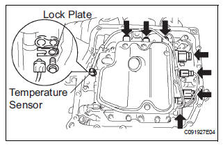
(a) Disconnect the 7 shift solenoid valve connectors.
(b) Remove the bolt and lock plate, and disconnect the ATF temperature sensor.
6. REMOVE VALVE BODY OIL STRAINER ASSEMBLY
(a) Remove the 3 bolts and oil strainer.
| NOTICE: Be careful when removing the oil strainer as fluid will come out. |
(b) Remove the O-ring from the valve body oil strainer assembly.
7. REMOVE TRANSMISSION VALVE BODY ASSEMBLY
(a) Support the valve body assembly and remove the 17 bolts and the transmission valve body assembly.
(b) Remove the check ball body and the spring.
(c) Remove the bolt and lock plate from the valve body assembly.
(d) Remove the shift solenoid valve SL3 and SLT from the valve body assembly.
(e) Remove the bolt and shift solenoid valve S4 from the valve body assembly
(f) Remove the shift solenoid valve SR from the valve body assembly.
(g) Remove the bolt and shift solenoid valve DSL from the valve body assembly.
(h) Remove the bolt and shift solenoid valve SL2 from the valve body assembly.
(i) Remove the bolt and shift solenoid valve SL1 from the valve body assembly.
 Valve body assembly
Components
...
 Installation
1. Install transmission valve body assembly
(a) Install the shift solenoid valve SL1 to the valve body
assembly with the bolt.
Torque: 6.6 N*m (67 kgf*cm, 58 in.*lbf)
(b) Install the shi ...
Other materials:
Wiper switch
COMPONENTS
REMOVAL
1. REMOVE STEERING COLUMN COVER
2. REMOVE WINDSHIELD WIPER SWITCH ASSEMBLY
Disconnect the connector.
Using a screwdriver, disengage the claw and pull
out the windshield wiper switch assembly.
NOTICE:
The claw will be broken if pressed hard.
HINT ...
Registering a Bluetooth®
audio player for the
first time
To use the Bluetooth® Audio, it is necessary to register an audio
player with the system.
Once the player has been registered, it is possible to use the
Bluetooth® Audio.
For details about registering a Bluetooth® device
Turn the Bluetooth® connection setting of your audio player on ...
On-vehicle inspection
1. CONNECT INTELLIGENT TESTER
(a) Connect the intelligent tester to the DLC3.
(b) Start the engine and run at idle.
(c) Select the ACTIVE TEST mode on the intelligent
tester.
HINT:
Please refer to the intelligent tester operator's
manual for further details.
2. INSPECT ACTUATOR MOTOR ...
