Toyota Sienna Service Manual: Installation
1. INSTALL TRANSFER EXTENSION HOUSING TYPE T OIL SEAL
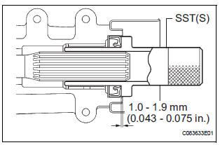
(a) Using SST(s), install anew transfer extension housing type T oil seal to he transfer extension housing sub-assembly at the position show in the illustration.
SST 09325-20010
NOTICE: Do not install the oil seal obliquely.
(b) Apply small amount of MP grease to the oil seal lip.
2. TEMPORARILY TIGHTEN PROPELLER WITH CENTER BEARING SHAFT ASSEMBLY
HINT: (See page PR-9)
3. FULLY TIGHTEN PROPELLER WITH CENTER BEARING SHAFT ASSEMBLY
HINT: (See page PR-9)
4. INSTALL FRONT EXHAUST PIPE ASSEMBLY
HINT: (See page EX-10)
5. INSTALL TRANSFER DRAIN PLUG
(a) Install the transfer drain plug with anew drain gasket.
Torque: 49 N*m (50 kgf*cm, 36 ft.*lbf)
6. INSTALL TRANSFER CASE NO.1 PLUG
(a) Add oil up to 0 to 5 mm (0 to 0.20 in.) below the lower side of the plug hole.
Oil amount: 0.9 L (0.95 US qts, 0.71 lmp.qts)
NOTICE: When supplying oil, pour do it slowly.
(b) Install the transfer case No. 1 plug with a new gasket No. 1.
Torque: 49 N*m (500 kgf*cm, 36 ft.*lbf)
7. CHECK FOR EXHAUST GAS LEAK
 Removal
1. REMOVE TRANSFER CASE NO.1 PLUG (See page
TF-8)
2. REMOVE TRANSFER DRAIN PLUG
(a) Remove the transfer drain plug, drain gasket and
bleed transfer oil.
3. REMOVE EXHAUST PIPE ASSEMBLY
HINT:
(S ...
 Propeller shaft
...
Other materials:
Center Airbag Sensor Assembly Malfunction
DTC B1100/31 Center Airbag Sensor Assembly Malfunction
DESCRIPTION
The center airbag sensor assembly consists of the center airbag sensor
assembly, safing sensor, drive
circuit, diagnosis circuit and ignition control, etc.
It receives signals from the airbag sensor, judges whether or not the ...
Front Clearance Sonar Sensor LH Circuit
DESCRIPTION
An ultrasonic sensor consists of a sensor portion that transmits and receives
ultrasonic waves and a preamplifier
that amplifies them. The ultrasonic sensor outputs the ultrasonic waves and
sends the received
signals to the clearance warning ECU.
WIRING DIAGRAM
INSPECTION PROC ...
Illumination Circuit
DESCRIPTION
The Multiplex network body ECU controls illumination light as shown in the
chart below.
Room light assembly (Interior light, luggage component light) and
courtesy light with DOOR position
Map light assembly (Personal light)
Transponder key amplifier (Ignition ke ...
