Toyota Sienna Service Manual: Throttle / Pedal Position Sensor / Switch "A" Circuit Range / Performance Problem
DTC P0121 Throttle / Pedal Position Sensor / Switch "A" Circuit Range / Performance Problem
HINT: This DTC relates to the Throttle Position (TP) sensor.
DESCRIPTION Refer to DTC P0120
|
DTC No. |
DTC Detection Condition |
Trouble Area |
|
P0121 |
Difference between VTA1 and VTA2 voltages less than 0.8 V, or more than 1.6 V for 2 seconds (1 trip detection logic) | TP sensor (built into throttle body) |
MONITOR DESCRIPTION
The ECM uses the TP sensor to monitor the throttle valve opening angle.
This sensor transmits two signals: VTA1 and VTA2. VTA1 is used to detect the throttle opening angle and VTA2 is used to detect malfunctions in VTA1. The ECM performs several checks to confirm the proper operation of the TP sensor and VTA1.
For each throttle opening angle, a specific voltage difference is expected between the outputs of VTA1 and VTA2. If the voltage output difference between the two signals deviates from the normal operating range, the ECM interprets this as a malfunction of the TP sensor. The ECM illuminates the MIL and sets the DTC.
If the malfunction is not repaired successfully, the DTC is set 2 seconds after the engine is next started.
MONITOR STRATEGY
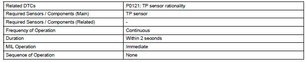
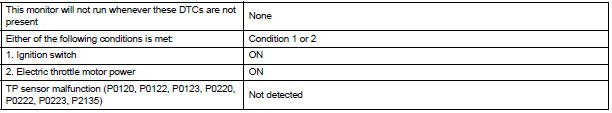
TYPICAL ENABLING CONDITIONS
TYPICAL MALFUNCTION THRESHOLDS

FAIL-SAFE
When this DTC, as well as other DTCs relating to ETCS (Electronic Throttle Control System) malfunctions, is set, the ECM enters fail-safe mode. During fail-safe mode, the ECM cuts the current to the throttle actuator off, and the throttle valve is returned to a 6.5 throttle angle by the return spring. The ECM then adjusts the engine output by controlling the fuel injection (intermittent fuel-cut) and ignition timing, in accordance with the accelerator pedal opening angle, to allow the vehicle to continue at a minimal speed. If the accelerator pedal is depressed slowly, the vehicle can be driven slowly.
Fail-safe mode continues until a pass condition is detected, and the ignition switch is then turned off.
INSPECTION PROCEDURE
HINT: Read freeze frame data using the intelligent tester. The ECM records vehicle and driving condition information as freeze frame data the moment a DTC is stored. When troubleshooting, freeze frame data can be helpful in determining whether the vehicle was running or stopped, whether the engine was warmed up or not, whether the air-fuel ratio was lean or rich, as well as other data recorded at the time of a malfunction.
1 CHECK ANY OTHER DTC OUTPUT (IN ADDITION TO DTC P0121)
- Connect the intelligent tester to the DLC3.
- Turn the ignition switch to the ON position.
- Turn the tester ON.
- Enter the following menus: DIAGNOSIS / ENHANCED OBD II / DTC INFO / CURRENT CODES.
- Read the DTC
Result

HINT: If any DTCs other than P0121 are output, troubleshoot those DTCs first.
REPLACE THROTTLE BODY
 Throttle / Pedal Position Sensor / Switch "A/B"
Circuit
Throttle / Pedal Position Sensor / Switch "A/B"
Circuit
DTC P0120 Throttle / Pedal Position Sensor / Switch "A"
Circuit
DTC P0122 Throttle / Pedal Position Sensor / Switch "A"
Circuit Low Input
DTC P0123 Throttle / Pedal Position Se ...
 Insufficient Coolant Temperature for Closed
Loop Fuel Control
Insufficient Coolant Temperature for Closed
Loop Fuel Control
DTC P0125 Insufficient Coolant Temperature for Closed
Loop Fuel Control
DESCRIPTION
Refer to DTC P0115
DTC No.
DTC Detection Condition
Trouble Area
P0125
E ...
Other materials:
Open in Rear Curtain Shield Squib LH Circuit
DTC B1636/88 Open in Rear Curtain Shield Squib LH Circuit
DESCRIPTION
The rear curtain shield squib LH circuit consists of the center airbag sensor
assembly and the curtain
shield airbag assembly LH.
The circuit instructs the SRS to deploy when deployment conditions are met.
DTC B1636/88 ...
Installation
1. INSTALL SHOCK ABSORBER ASSEMBLY REAR LH
(a) Install the rear spring bumper No.1 LH to the shock
absorber assembly LH.
(b) Support the rear axle beam assembly with a jack.
(c) Install the rear shock absorber assembly rear LH,
cushion retainer and nut to the rear axle beam.
(d) ...
Inspection
1. Inspect starter assembly
NOTICE:
These tests must be performed within 3 to 5 seconds
to avoid burning out the coil.
(a) Perform the pull-in test.
(1) Disconnect the lead wire from terminal C.
(2) Connect the battery to the magnetic switch as
shown in the illustratio ...
