Toyota Sienna Service Manual: Low Battery Positive Voltage
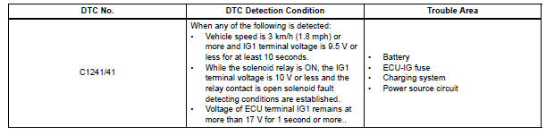
DTC C1241/41 Low Battery Positive Voltage
DESCRIPTION
If there is a problem with the brake actuator assembly (skid control ECU) power supply circuit, the skid control ECU outputs the DTC and prohibits the ABS operation with the fail safe function.
If the voltage supplied to the IG1 terminal is not within the DTC detection threshold due to malfunctions in such as the battery and alternator circuit, this DTC is stored.
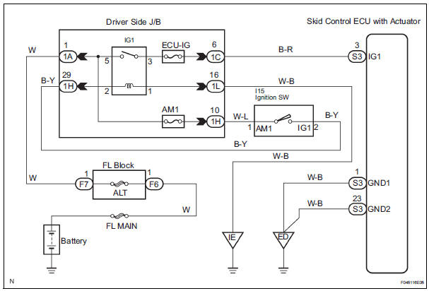
WIRING DIAGRAM
INSPECTION PROCEDURE
HINT: After steps 1 and 2 are completed, start the inspection from step 3 when using the intelligent tester, and from step 4 when not using the intelligent tester.
1 INSPECT BATTERY
(a) Check the battery voltage.
Standard voltage: 11 to 14 V


2 INSPECT FUSE (ECU-IG FUSE)
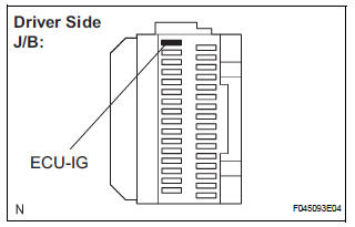
(a) Remove the ECU-IG fuse from the driver side J/B.
(b) Measure the resistance according to the value(s) in the table below.
Standard resistance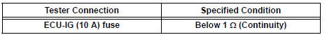

3 READ VALUE OF INTELLIGENT TESTER (IG1 POWER SUPPLY)
(a) Install the ECU-IG fuse.
(b) Connect the intelligent tester to the DLC3.
(c) Turn the ignition switch to the ON position and turn the intelligent tester main switch on.
(d) Start the engine.
(e) Select the DATA LIST mode on the intelligent tester.
ABS: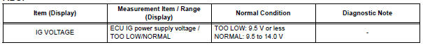
(f) Measure the voltage output from the ECU displayed on the intelligent tester.
OK: "Normal" is displayed.

4 INSPECT SKID CONTROL ECU (IG1 TERMINAL VOLTAGE)
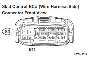
(a) Disconnect the skid control ECU connector.
(b) Turn the ignition switch to ON position.
(c) Measure the voltage according to the value(s) in the table below.
Standard voltage 

5 INSPECT SKID CONTROL ECU (GND TERMINAL CONTINUITY)
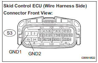
(a) Turn the ignition switch off.
(b) Measure the resistance according to the value(s) in the table below.
Standard resistance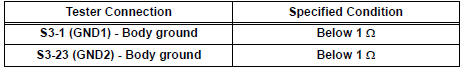

6 RECONFIRM DTC
(a) Clear the DTCs (See page BC-10).
(b) Check that the same DTC is recorded (See page BC- 10).
HINT: Reinstall the sensors, connectors, etc. and restore the vehicle to its prior condition before rechecking for DTCs.
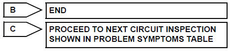
Result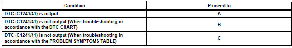

REPLACE BRAKE ACTUATOR ASSEMBLY
 Open in ABS Solenoid Relay Circuit
DESCRIPTION
This relay supplies power to each ABS solenoid.
Immediately after the ignition switch is turned to the ON position, the relay
turns on if the solenoid is
determined to be normal ...
 Open in Stop Light Switch Circuit
DTC C1249/49 Open in Stop Light Switch Circuit
DESCRIPTION
This skid control ECU inputs the stop light switch signal and detects the
status of brake operation.
The skid control ECU has an open ...
Other materials:
Identification information
VEHICLE IDENTIFICATION AND SERIAL NUMBERS
1. VEHICLE IDENTIFICATION NUMBER
(a) The vehicle identification number is stamped on the
vehicle identification number plate and the
certification label, as shown in the illustration.
A:
Vehicle Identification Number Plate
B:
...
Audio system types
Entune Audio
Entune Audio Plus/Entune Premium Audio with Navigation
Owners of models equipped with a navigation system should refer to
the “NAVIGATION AND MULTIMEDIA SYSTEM OWNER’S
MANUAL”.
Using cellular phones
Interference may be heard through the audio system’s speakers if a c ...
Past record
Type A
Press the “CAR” button.
Type B
Press the “APPS” button, and then select “Eco” on the screen.
If the “Trip Information” screen is displayed, select “Past Record”.
Reset the past record data
Best recorded fuel consumption
Average fuel consumption ...
