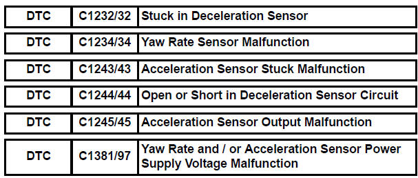
Toyota Sienna Service Manual: Stuck in Deceleration Sensor
DESCRIPTION
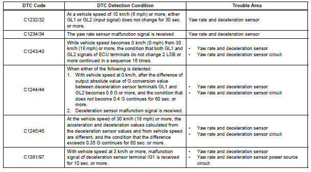
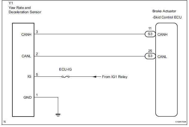
The yaw rate sensor and deceleration sensor signal is sent to the skid control ECU through the CAN communication system. When there is a malfunction in the communication, it will be detected by the diagnosis function.
WIRING DIAGRAM
INSPECTION PROCEDURE
HINT: When U0073/94, U0100/65, U0123/62, U0124/95 or U0126/63 are output accompanied with C1232/32, C1234/34, C1243/43, C1244/44, C1245/45 or C1381/97, inspect and repair the trouble areas indicated by U0073/94, U0100/65, U0123/62, U0124/95 or U0126/63 first.
1 CHECK YAW RATE AND DECELERATION SENSOR INSTALLATION
(a) Check that the yaw rate and deceleration sensor has been installed properly (See page BC-197).
OK: The sensor should be tightened to the specified torque.
The sensor should not be tilted.

2 INSPECT YAW RATE AND DECELERATION SENSOR (IG TERMINAL)
(a) Disconnect the yaw rate and deceleration sensor connector.
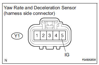
(b) Turn the ignition switch to the ON position.
(c) Measure the voltage according to the value(s) in the table below.
Standard voltage 

3 INSPECT YAW RATE AND DECELERATION SENSOR (GND TERMINAL)
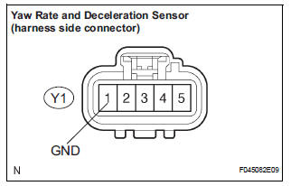
(a) Disconnect the yaw rate and deceleration sensor connector.
(b) Measure the resistance according to the value(s) in the table below.
Standard resistance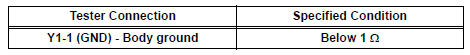

REPLACE YAW RATE AND DECELERATION SENSOR
 Steering Angle Sensor Circuit Malfunction
DTC C1231/31 Steering Angle Sensor Circuit Malfunction
DESCRIPTION
The steering angle sensor signal is sent to the skid control ECU through the
CAN communication system.
When there is a malfunc ...
 Low Battery Positive Voltage
DTC C1241/41 Low Battery Positive Voltage
DESCRIPTION
WIRING DIAGRAM
INSPECTION PROCEDURE
1 INSPECT ECU-IG FUSE
(a) Remove the ECU-IG fuse from the driver side J/B.
(b) Check continu ...
Other materials:
Installation
1. INSTALL FRONT DOOR WINDOW FRAME MOULDING
Remove the tape from the front door window frame
moulding.
Clean the contact surface of the vehicle body with
white gasoline.
Clean the outer circumference of the front door
window frame moulding with white gasoline.
Apply new double-si ...
Drive information
Average fuel economy*1, 2
Displays the average fuel consumption since the function was
reset.*3
Tank average fuel economy*1, 2
Displays the average fuel consumption since the vehicle was refueled.
Trip average fuel economy*1, 2
Displays the average fuel consumption since the engine wa ...
Diagnosis system
1. DIAGNOSIS FUNCTION
The diagnosis function makes the light and the
multi-information display come on, and the CRUISE
main indicator light blink as shown in the illustration.
When a malfunction occurs in the dynamic laser
cruise control system, the DTCs are stored in the
ECM ...
