Toyota Sienna Service Manual: Open in Stop Light Switch Circuit
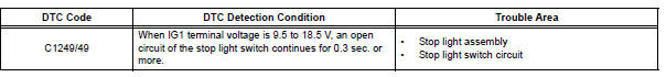
DTC C1249/49 Open in Stop Light Switch Circuit
DESCRIPTION
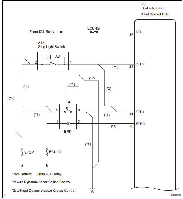
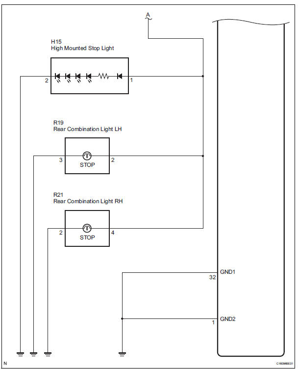
WIRING DIAGRAM
INSPECTION PROCEDURE
1 CHECK STOP LIGHT SWITCH OPERATION
(a) Check that the stop light comes on when the brake pedal is depressed and goes off when the brake pedal is released.
OK 
HINT: Check the stop light bulb as it may have burnt out.

2 INSPECT SKID CONTROL ECU (STP1 TERMINAL)
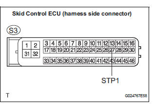
(a) Disconnect the skid control ECU connector.
(b) Measure the voltage according to the value(s) in the table below.
Standard voltage 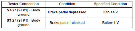

3 RECONFIRM DTC
(a) Clear the DTCs (See page BC-82).
(b) Turn the ignition switch to the ON position.
(c) Are the same DTCs detected?
Result 
NOTICE: When replacing the brake actuator assembly, perform zero point calibration (See page BC-70).

REPLACE BRAKE ACTUATOR ASSEMBLY
4 INSPECT STOP LIGHT SWITCH
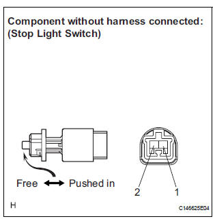
(a) Disconnect the stop light switch assembly connector.
(b) Measure the resistance according to the value(s) in the table below.
Standard resistance 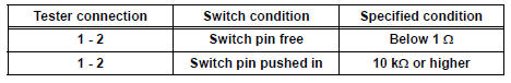


5 CHECK HARNESS AND CONNECTOR (STOP LIGHT SWITCH - SKID CONTROL ECU)
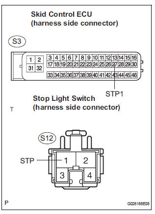
(a) Disconnect the stop light switch connector and skid control ECU connector.
(b) Measure the resistance according to the value(s) in the table below.
Standard resistance 
NOTICE: When replacing the brake actuator assembly, perform zero point calibration (See page BC-70).

REPLACE BRAKE ACTUATOR ASSEMBLY
 Master Cylinder Pressure Sensor Malfunction
DTC C1246/46 Master Cylinder Pressure Sensor Malfunction
DESCRIPTION
Master cylinder pressure sensor is connected to the skid control ECU in the
actuator.
INSPECTION PROCEDURE
1 READ VALUE O ...
 Open in Pump Motor Circuit
DTC C1251/51 Open in Pump Motor Circuit
DESCRIPTION
WIRING DIAGRAM
INSPECTION PROCEDURE
1 PERFORM ACTIVE TEST USING INTELLIGENT TESTER (ABS MOTOR RELAY)
(a) Connect the intelligent tester ...
Other materials:
Short to GND in Front Pretensioner Squib RH
Circuit
DTC B0132/61 Short to GND in Front Pretensioner Squib RH
Circuit
DESCRIPTION
The front pretensioner squib RH circuit consists of the center airbag sensor
assembly and the front seat
outer belt assembly RH.
This circuit instructs the SRS to deploy when deployment conditions are met.
DTC B ...
The Rear Cross Traffic Alert function detection areas
The areas that vehicles can be detected in are outlined below.
To give the driver a more consistent time to react, the buzzer can alert
for faster vehicles from farther away.
Example:
The Rear Cross Traffic Alert function is operational when
The BSM main switch is set to on.
The ...
Pre-collision seat belts (front seats of vehicles with pre-collision
system)
If the system determines that a collision is unavoidable, the front seat
belts will retract before the collision.
Emergency locking retractor (ELR)
The retractor will lock the belt during a sudden stop or on impact. It may
also
lock if you lean forward too quickly. A slow, easy motion wi ...
