Toyota Sienna Service Manual: Master Error
DTC 01-DF Master Error
DESCRIPTION
|
DTC No. |
DTC Detection Condition |
Trouble Area |
| 01-DF *1 |
|
|
HINT: *1: When 210 seconds have elapsed after disconnecting the power supply connector of the master component with the ignition switch in the ACC or ON position, this code is stored.
NOTICE:
- Before starting troubleshooting, be sure to clear DTCs to erase codes stored due to the reasons described in the HINT above. Then, check for DTCs and troubleshoot according to the output DTCs.
- The radio and navigation assembly is the master unit.
- Be sure to clear and recheck DTCs after the inspection is completed to confirm that no DTCs are output.
INSPECTION PROCEDURE
NOTICE: Be sure to read DESCRIPTION before performing the following procedures.
1 CHECK RADIO AND NAVIGATION ASSEMBLY POWER SOURCE CIRCUIT
Refer to the radio and navigation assembly power source circuit.
If the power source circuit is operating normally, proceed to the next step.
2 INSPECT RADIO AND NAVIGATION ASSEMBLY
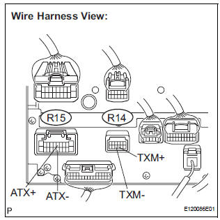
- Disconnect the radio and navigation assembly connectors.
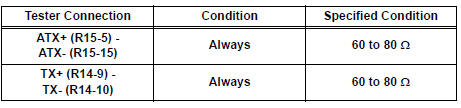
- Measure the resistance according to the value(s) in the table below.
Standard resistance
3 IDENTIFY THE COMPONENT WHICH HAS STORED THIS CODE
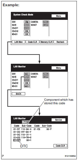
- Enter the diagnostic mode.
- Press the "LAN Mon" switch to change to "LAN Monitor" mode.
- Identify the component which has stored this code.
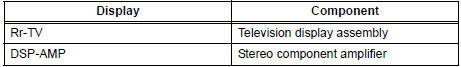
Component Table:
HINT: "NAVI" is the component which has stored this code in the example shown in the illustration.
4 CHECK HARNESS AND CONNECTOR
HINT: For details of the connectors, refer to "TERMINALS OF ECU".
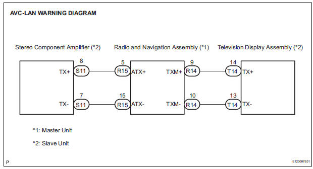
- Referring to the AVC-LAN wiring diagram below, check the AVC-LAN circuit between the radio and navigation assembly and the component which has stored this code.
- Disconnect all connectors between the radio and navigation assembly and the component which has stored this code.
- Check for an open or short in the AVC-LAN circuit between the radio and navigation assembly and the component which has stored this code.
OK: There is no open or short circuit.
5 REPLACE RADIO AND NAVIGATION ASSEMBLY
- Replace the radio and navigation assembly with a normal one and check if the same problem occurs again.
OK: Same problem does not occur
END
 Master Reset/ Voice Processing Device ON Error
DTC 01-DD Master Reset
DTC 01-E1 Voice Processing Device ON
DESCRIPTION
DTC No.
DTC Detection Condition
Trouble Area
01-DD
*1
The device that should be the m ...
 Registration Complete Indication Error/ Registration Demand Transmission/
Multiple Frame Incomplete
Registration Complete Indication Error/ Registration Demand Transmission/
Multiple Frame Incomplete
DTC 01-E0 Registration Complete Indication Error
DTC 01-E3 Registration Demand Transmission
DTC 01-E4 Multiple Frame Incomplete
DESCRIPTION
DTC No.
DTC Detection Condition
...
Other materials:
Opening the back door from outside the vehicle
Back door opener
Raise the back door while
pressing the back door opener
to release the lock to open the
back door.
Wireless remote control (vehicles with power back door)
Press and hold the switch to open/close the power back door
Vehicles without a smart key
system
Vehicl ...
Setting the vehicle speed (vehicle-to-vehicle distance control
mode)
Press the “ON-OFF” button to
activate the cruise control.
Dynamic radar cruise control indicator
will be displayed.
Press the button again to deactivate
the cruise control.
Accelerate or decelerate the
vehicle to the desired speed,
and push the lever down to set
...
Speed Signal Circuit
DESCRIPTION
The clearance warning ECU receives the vehicle speed signal from the
combination meter.
HINT:
A voltage of 12 V or 5 V is output from each ECU and then input to
the combination meter. The signal
is changed to a pulse signal at the transistor in the combination meter.
...
