Toyota Sienna Service Manual: Intake Air Temperature Circuit
DESCRIPTION
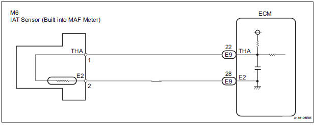
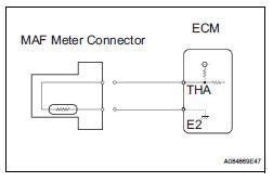
The Intake Air Temperature (IAT) sensor, mounted on the Mass Air Flow (MAF) meter, monitors the IAT.
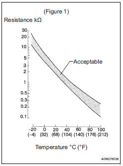
The IAT sensor has a built-in thermistor with a resistance that varies according to the temperature of the intake air. When the IAT is low, the resistance of the thermistor increases. When the temperature is high, the resistance drops. These variations in resistance are transmitted to the ECM as voltage changes (see Fig. 1).
The IAT sensor is powered by a 5 V applied from the THA terminal of the ECM, via resistor R.
Resistor R and the IAT sensor are connected in series. When the resistance value of the IAT sensor changes, according to changes in the IAT, the voltage at terminal THA also varies. Based on this signal, the ECM increases the fuel injection volume when the engine is cold to improve driveability.
HINT:
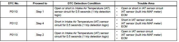
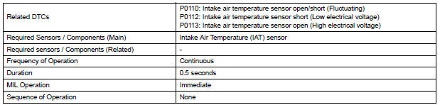
When any of DTCs P0110, P0112 and P0113 are set, the ECM enters fail-safe mode. During fail-safe mode, the IAT is estimated to be 20°C (68°F) by the ECM. Fail-safe mode continues until a pass condition is detected.
HINT:
When any of these DTCs are set, check the IAT by selecting the following menu items on the intelligent tester: DIAGNOSIS / ENHANCED OBD II / DATA LIST / PRIMARY / INTAKE AIR.

MONITOR DESCRIPTION
The ECM monitors the sensor voltage and uses this value to calculate the Intake Air Temperature (IAT).
When the sensor output voltage deviates from the normal operating range, the ECM interprets this as a malfunction in the IAT sensor and sets a DTC.
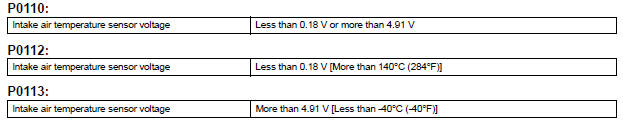
Example: If the sensor voltage output is -40°C (-40°F) for 0.5 seconds or more, the ECM determines that there is an open in the IAT sensor circuit, and sets DTC P0113. Conversely, if the voltage output is more than 140°C (284°F) for 0.5 seconds or more, the ECM determines that there is a short in the sensor circuit, and sets DTC P0112.
If the malfunction is not repaired successfully, a DTC is set 0.5 seconds after the engine is next started.
MONITOR STRATEGY
TYPICAL ENABLING CONDITIONS

TYPICAL MALFUNCTION THRESHOLDS
COMPONENT OPERATING RANGE

WIRING DIAGRAM
INSPECTION PROCEDURE
HINT:
- If other DTCs relating to different systems that have terminal E2 as the ground terminal are output simultaneously, terminal E2 may have an open circuit.
- Read freeze frame data using the intelligent tester. The ECM records vehicle and driving condition information as freeze frame data the moment a DTC is stored. When troubleshooting, freeze frame data can be helpful in determining whether the vehicle was running or stopped, whether the engine was warmed up or not, whether the air-fuel ratio was lean or rich, as well as other data recorded at the time of a malfunction.
1 READ VALUE OF INTELLIGENT TESTER (INTAKE AIR TEMPERATURE)
(a) Connect the intelligent tester to the DLC3.
(b) Turn the ignition switch to the ON position.
(c) Turn the tester on.
(d) Select the following menu items: DIAGNOSIS / ENHANCED OBD II / DATA LIST / PRIMARY / INTAKE AIR.
(e) Read the value displayed on the tester.
Standard: Same as actual Intake Air Temperature (IAT).
Result 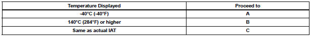
HINT:
- If there is an open circuit, the intelligent tester indicates -40°C (-40°F).
- If there is a short circuit, the intelligent tester indicates 140°C (284°F) or higher.


2 READ VALUE OF INTELLIGENT TESTER (CHECK FOR OPEN IN WIRE HARNESS)
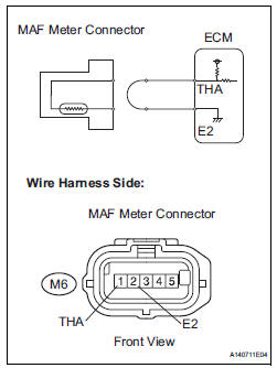
(a) Disconnect the M6 Mass Air Flow (MAF) meter connector.
(b) Connect terminals THA and E2 of the MAF meter wire harness side connector.
(c) Connect the intelligent tester to the DLC3.
(d) Turn the ignition switch to the ON position.
(e) Turn the tester on.
(f) Select the following menu items: DIAGNOSIS / ENHANCED OBD II / DATA LIST / PRIMARY / INTAKE AIR.
(g) Read the value displayed on the tester.
Standard: 140°C (284°F) or higher
(h) Reconnect the MAF meter connector.

3 CHECK HARNESS AND CONNECTOR (MASS AIR FLOW METER - ECM)
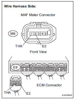
(a) Disconnect the M6 MAF meter connector.
(b) Disconnect the E9 ECM connector.
(c) Measure the resistance according to the value(s) in the table below.
Standard resistance: 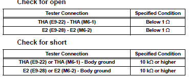
(d) Reconnect the MAF meter connector.
(e) Reconnect the ECM connector.

REPLACE ECM (See page ES-498)
4 READ VALUE OF INTELLIGENT TESTER (CHECK FOR SHORT IN WIRE HARNESS)
(a) Disconnect the M6 MAF meter connector.
(b) Connect the intelligent tester to the DLC3.
(c) Turn the ignition switch to the ON position.
(d) Turn the tester on.
(e) Select the following menu items: DIAGNOSIS / ENHANCED OBD II / DATA LIST / PRIMARY / INTAKE AIR.
(f) Read the value displayed on the tester.
Standard: -40°C (-40°F)
(g) Reconnect the MAF meter connector.


5 CHECK HARNESS AND CONNECTOR (MASS AIR FLOW METER - ECM)
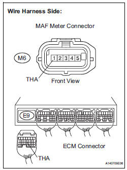
(a) Disconnect the M6 MAF meter connector.
(b) Disconnect the E9 ECM connector.
(c) Measure the resistance according to the value(s) in the table below.
Standard resistance 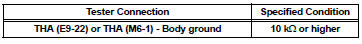
(d) Reconnect the MAF meter connector.
(e) Reconnect the ECM connector.

REPLACE ECM (See page ES-498)
 Mass or Volume Air Flow Circuit Range / Performance Problem
DESCRIPTION
Refer to DTC P0100 (See page ES-116).
MONITOR DESCRIPTION
The MAF meter is a sensor that measures the amount of air flowing through the
throttle valve. The ECM
uses this info ...
 Intake Air Temperature Sensor Gradient Too High
DESCRIPTION
The Intake Air Temperature (IAT) sensor, mounted on the Mass Air Flow (MAF)
meter, monitors the IAT.
The IAT sensor has a built-in thermistor with a resistance that varies ac ...
Other materials:
Scratched / Reversed Disc
DTC 62-46 Scratched / Reversed Disc
DTC 63-46 Scratched / Reversed Disc
DESCRIPTION
DTC No.
DTC Detecting Condition
Trouble Area
62-46
Scratches or dirt is found on CD surface or CD is set
upside down.
CD
Radio receiver
...
Problem symptoms table
HINT:
Before performing verification listed in the table below,
check the fuse and relay.
Check the circuits for each problem symptom in the order
given in the table below, and proceed to the relevant page.
CLEARANCE SONAR SYSTEM:
*1: with Front Clearance Sonar
*2: wit ...
If the engine will not
start
If the engine will not start even though correct starting procedures
are being followed (, 228), consider each of the following
points:
The engine will not start even though the starter motor operates
normally.
One of the following may be the cause of the problem:
There may not be sufficien ...
