Toyota Sienna Service Manual: Knock Sensor 1 Circuit Low Input
DESCRIPTION
A flat type knock sensor (non-resonant type) has a structure that can detect vibrations over a wide band of frequencies: between approximately 6 kHz and 15 kHz.
Knock sensors are fitted onto the engine block to detect engine knocking.
The knock sensor contains a piezoelectric element which generates a voltage when the engine block vibrates due to knocking. Any occurrence of engine knocking can be suppressed by delaying the ignition timing.
HINT:
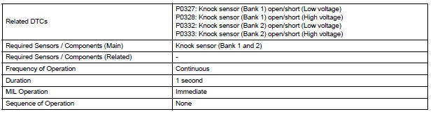
When any of DTCs P0327, P0328, P0332 and P0333 are set, the ECM enters fail-safe mode. During failsafe mode, the ignition timing is delayed to its maximum retardation. Fail-safe mode continues until the ignition switch is turned off.
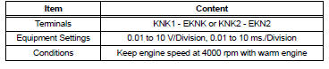
Reference: Inspection using an oscilloscope
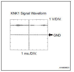
The correct waveform is as shown.
MONITOR DESCRIPTION
The knock sensor, located on the cylinder block, detects spark knock. When a spark knock occurs, the piezoelectric element of the sensor vibrates. When the ECM detects a voltage in this frequency range, it retards the ignition timing to suppress the spark knock.
The ECM also senses background engine noise with the knock sensor and uses this noise to check for faults in the sensor. If the knock sensor signal level is too low for more than 10 seconds, or if the knock sensor output voltage is outside the normal range, the ECM interprets this as a fault in the knock sensor and sets a DTC.
MONITOR STRATEGY
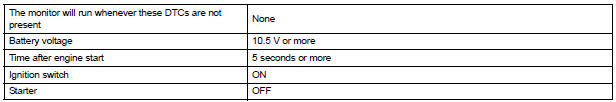
TYPICAL ENABLING CONDITIONS
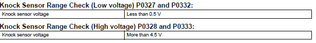
TYPICAL MALFUNCTION THRESHOLDS
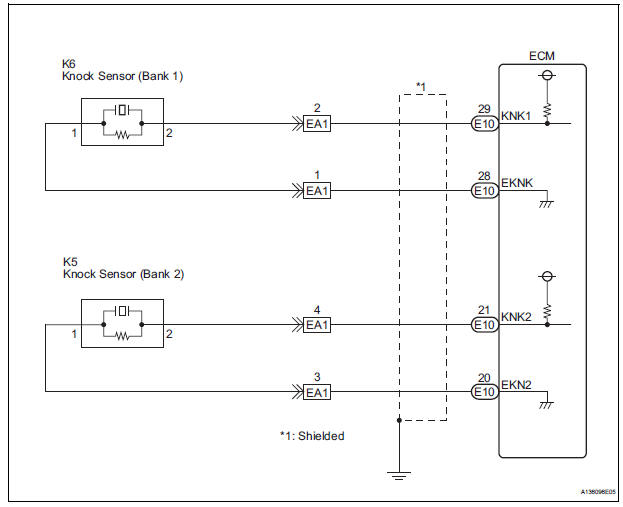
WIRING DIAGRAM
INSPECTION PROCEDURE
HINT:
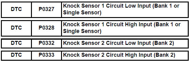
- DTCs P0327 and P0328 are for the bank 1 knock sensor circuit.
- DTCs P0332 and P0333 are for the bank 2 knock sensor circuit.
- Read freeze frame data using the intelligent tester. The ECM records vehicle and driving condition information as freeze frame data the moment a DTC is stored. When troubleshooting, freeze frame data can be helpful in determining whether the vehicle was running or stopped, whether the engine was warmed up or not, whether the air-fuel ratio was lean or rich, as well as other data recorded at the time of a malfunction.
1 READ VALUE OF DTC OUTPUT (CHECK KNOCK SENSOR CIRCUIT)
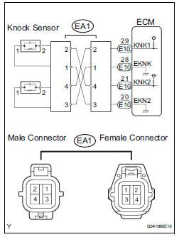
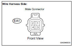
(a) Disconnect the EA1 connector.
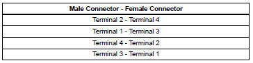
(b) Using lead wires, connect the connectors as follows.
(c) Warm up the engine.
(d) Run the engine at 3000 rpm for 10 seconds or more.
(e) Connect the intelligent tester to the DLC3.
(f) Turn the ignition switch to the ON position and turn the intelligent tester on.
(g) Select the items: DIAGNOSIS / ENHANCED OBD II / DTC INFO / CURRENT CODES.
(h) Read the DTCs.
Result 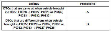
(i) Reconnect the EA1 connector.


2 CHECK HARNESS OR CONNECTOR (EA1 CONNECTOR - ECM)
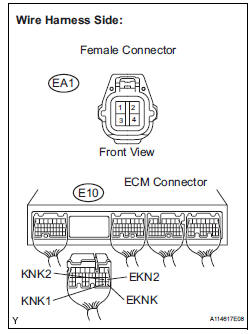
(a) Disconnect the EA1 connector.
(b) Disconnect the E10 ECM connector.
(c) Measure the resistance according to the value(s) in the table below.
Standard resistance: 
(d) Reconnect the EA1 connector.
(e) Reconnect the ECM connector.

3 INSPECT ECM
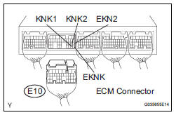
(a) Disconnect the E10 ECM connector.
(b) Turn the ignition switch to the ON position.
(c) Measure the voltage according to the value(s) in the table below.
Standard voltage 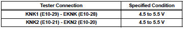
d) Reconnect the ECM connector.
| NOTICE: Fault may be intermittent. Check the wire harness and connectors carefully and retest. |

CHECK FOR INTERMITTENT PROBLEMS
4 INSPECT KNOCK SENSOR
(a) Disconnect the EA1 connector.
(b) Measure the resistance according to the value(s) in the table below.
Standard resistance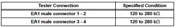
(c) Reconnect the EA1 connector.

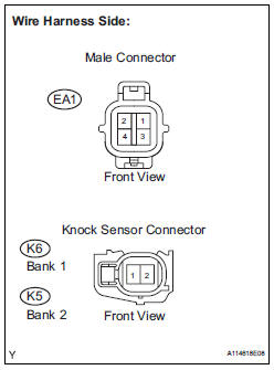
5 CHECK HARNESS AND CONNECTOR (EA1 CONNECTOR - KNOCK SENSOR)
HINT:
- If DTC P0327 or P0328 has changed to P0332 or P0333, check the knock sensor circuit on the right bank side.
- If DTC P0332 or P0333 has changed to P0327 or P0328, check the knock sensor circuit on the left bank side.
(a) Disconnect the EA1 connector.
(b) Disconnect the K6 and K5 knock sensor connectors.
(c) Measure the resistance according to the value(s) in the table below.
Standard resistance: 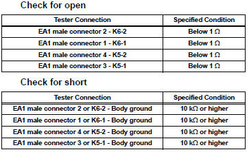
(d) Reconnect the EA1 connector.
(e) Reconnect the knock sensor connector.

REPLACE KNOCK SENSOR (See page ES-520)
 Random / Multiple Cylinder Misfire Detected
DESCRIPTION
When the engine misfires, high concentrations of hydrocarbons (HC) enter the
exhaust gas. High HC
concentration levels can cause increase in exhaust emission levels. Extremely ...
 Crankshaft Position Sensor
DESCRIPTION
The Crankshaft Position (CKP) sensor system consists of a CKP sensor plate
and a pickup coil. The
sensor plate has 34 teeth and is installed on the crankshaft. The pickup coil is
...
Other materials:
Calculation formula for your vehicle
Cargo capacity
Total load capacity (vehicle capacity weight)
When 2 people with the combined weight of A lb. (kg) are riding in
your vehicle, which has a total load capacity (vehicle capacity weight)
of B lb. (kg), the available amount of cargo and luggage load capacity
will be C lb. ...
Air conditioning controls
Adjusting the temperature setting
Press ÔÇťÔÇŁ on the ÔÇťTEMPÔÇŁ button to
increase the temperature and ÔÇťÔÇŁ
to decrease the temperature.
Adjusting the fan speed
Press ÔÇťÔÇŁ on
to increase the fan speed and ÔÇťÔÇŁ
to decrease
the fan speed.
Press the ÔÇťOFFÔÇŁ button to turn the ...
Inspection procedure
1 BASIC INSPECTION
Check the conditions necessary for the power slide door
to open:
Power slide door main switch is in the ON position
(switch free: orange paint on the top of the switch
appears).
Slide door is unlocked (door lock position switch is
in the ON position when ...
