Toyota Sienna Service Manual: VC Output Circuit
DESCRIPTION
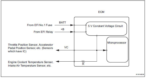
The ECM constantly uses 5 V from the battery voltages supplied to the +B (BATT) terminal to operate the microprocessor. The ECM also provides this power to the sensors through the VC output circuit.
When the VC circuit is short-circuited, the microprocessor in the ECM and sensors that are supplied power through the VC circuit are inactivated because the power is not supplied from the VC circuit. Under this condition, the system does not start up and the MIL does not illuminate even if the system malfunctions.
HINT:
Under normal conditions, the MIL is illuminated for several seconds when the ignition switch is first turned to the ON position. The MIL goes off when the engine is started.
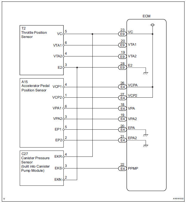
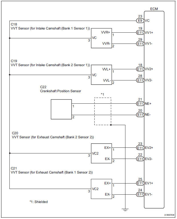
WIRING DIAGRAM
INSPECTION PROCEDURE
1 CHECK MIL
(a) Check that the Malfunction Indicator Lamp (MIL) lights up when turning the ignition switch to the ON position.
OK: MIL lights up.


2 CHECK CONNECTION BETWEEN INTELLIGENT TESTER AND ECM
(a) Connect the intelligent tester to the DLC3.
(b) Turn the ignition switch to the ON position and turn the tester on.
(c) Check the communication between the tester and ECM.
Result 


3 CHECK THROTTLE BODY (CHECK MIL ILLUMINATED)
(a) Disconnect the throttle body connector.
(b) Turn the ignition switch to the ON position.
(c) Check the MIL.
Result
(d) Reconnect the throttle body connector.

4 CHECK ACCELERATOR PEDAL ROD (CHECK MIL ILLUMINATED)
(a) Disconnect the accelerator pedal position sensor connector.
(b) Turn the ignition switch to the ON position.
(c) Check the MIL.
Result 
(d) Reconnect the accelerator pedal position sensor connector.

5 CHECK VVT SENSOR FOR INTAKE CAMSHAFT BANK 1 (CHECK MIL ILLUMINATED)
(a) Disconnect the VVT sensor for intake camshaft bank 1 connector.
(b) Turn the ignition switch to the ON position.
(c) Check the MIL.
Result 
(d) Reconnect the VVT sensor for intake camshaft bank 1 connector.

6 CHECK VVT SENSOR FOR EXHAUST CAMSHAFT BANK 1 (CHECK MIL ILLUMINATED)
(a) Disconnect the VVT sensor for exhaust camshaft bank 1 connector.
(b) Turn the ignition switch to the ON position.
(c) Check the MIL.
Result 
(d) Reconnect the VVT sensor for exhaust camshaft bank 1 connector.

7 CHECK VVT SENSOR FOR INTAKE CAMSHAFT BANK 2 (CHECK MIL ILLUMINATED)
(a) Disconnect the VVT sensor for intake camshaft bank 2 connector.
(b) Turn the ignition switch to the ON position.
(c) Check the MIL.
Result 
(d) Reconnect the VVT sensor for intake camshaft bank 2 connector.

8 CHECK VVT SENSOR FOR EXHAUST CAMSHAFT BANK 2 (CHECK MIL ILLUMINATED)
(a) Disconnect the VVT sensor for exhaust camshaft bank 2 connector.
(b) Turn the ignition switch to the ON position.
(c) Check the MIL.
Result 
(d) Reconnect the VVT sensor for exhaust camshaft bank 2 connector.

9 CHECK CHARCOAL CANISTER ASSEMBLY (CHECK MIL ILLUMINATED)
(a) Disconnect the canister pump module connector.
(b) Turn the ignition switch to the ON position.
(c) Check the MIL.
Result 
(d) Reconnect the canister pump module connector.

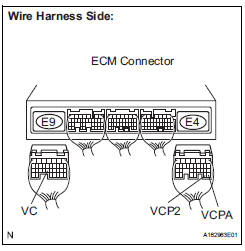
10 CHECK HARNESS AND CONNECTOR
(a) Disconnect the throttle body connector.
(b) Disconnect the accelerator pedal position sensor connector.
(c) Disconnect the VVT sensor for intake camshaft bank 1 connector.
(d) Disconnect the VVT sensor for exhaust camshaft bank 1 connector.
(e) Disconnect the VVT sensor for intake camshaft bank 2 connector.
(f) Disconnect the VVT sensor for exhaust camshaft bank 2 connector.
(g) Disconnect the canister pump module connector.
(h) Disconnect the E9 and E4 ECM connectors.
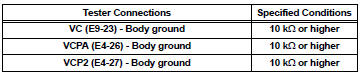
(i) Measure the resistance according to the value(s) in the table below.
Standard resistance (Check for short)
(j) Reconnect the ECM connectors.
(k) Reconnect the canister pump module connector.
(l) Reconnect the VVT sensor for exhaust camshaft bank 2 connector.
(m) Reconnect the VVT sensor for intake camshaft bank 2 connector.
(n) Reconnect the VVT sensor for exhaust camshaft bank 1 connector.
(o) Reconnect the VVT sensor for intake camshaft bank 1 connector.
(p) Reconnect the accelerator pedal position sensor connector.
(q) Reconnect the throttle body connector.


REPLACE ECM (See page ES-498)
 ECM Power Source Circuit
DESCRIPTION
When the ignition switch is turned to the ON position, the battery voltage is
applied to terminal IGSW of
the ECM. The ECM MREL output signal causes a current to flow to the coil,
cl ...
 Fuel Pump Control Circuit
DESCRIPTION
The FUEL PUMP relay switches the fuel pump speed according to the engine
conditions. The fuel pump
operates when the ECM receives the starter-operating signal (STA) and
crankshaft-ro ...
Other materials:
Armrests
Pull the armrest down for use.
Front seat
Second seat (if equipped)
Adjusting the front seat armrests (if equipped)
Push the armrest down while pressing the
button.
NOTICE
To prevent damage to the armrest, do not apply too much load on the
armrest.
...
Throttle Actuator Control Motor Circuit
DESCRIPTION
The throttle actuator is operated by the ECM and opens and closes the
throttle valve using gears.
The opening angle of the throttle valve is detected by the Throttle Position
(TP) sensor, which is mounted
on the throttle body. The TP sensor provides feedback to the ECM. This ...
Rear Occupant Classification Sensor RH Collision
Detection
DTC B1788 Rear Occupant Classification Sensor RH Collision
Detection
DESCRIPTION
DTC B1788 is output when the occupant classification ECU receives a collision
detection signal sent by
the rear occupant classification sensor RH if an accident occurs.
DTC B1788 is also output when the front s ...
