Toyota Sienna Service Manual: Transmission Fluid Temperature Sensor "A" Performance

DESCRIPTION
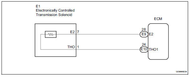
The ATF (Automatic Transmission Fluid) temperature sensor converts the fluid temperature into a resistance value which is input into the ECM.
MONITOR DESCRIPTION
The ATF temperature sensor converts the ATF temperature to an electrical resistance value. Based on the resistance, the ECM determines the ATF temperature and detects an open or short in the ATF temperature circuit or a fault in the ATF temperature sensor.
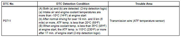
After running the vehicle for a certain period, the ATF temperature should increase. If the ATF temperature is below 20°C (68°F) after running the vehicle for a certain period, the ECM interprets this as a fault, and turns on the MIL.
When the ATF temperature is 110°C (230°F) or more after 17 minutes of engine cold start, the ECM also determines this as a fault, turns on the MIL, and stores the DTC.
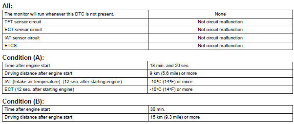
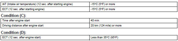
MONITOR STRATEGY

TYPICAL ENABLING CONDITIONS
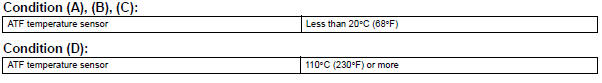
TYPICAL MALFUNCTION THRESHOLDS
COMPONENT OPERATING RANGE

WIRING DIAGRAM
INSPECTION PROCEDURE
HINT: Using the intelligent tester to read the DATA LIST allows the values or states of switches, sensors, actuators and other items to be read without removing any parts. This non-intrusive inspection can be very useful because intermittent conditions or signals may be discovered before parts or wiring is disturbed. Reading the DATA LIST information early in troubleshooting is one way to save diagnostic time.
| NOTICE: In the table below, the value listed under "Normal Condition" are reference values. Do not depend solely on these reference values when deciding whether apart is faulty or not. |
1. READ DATA LIST
(a) Warm up the engine.
(b) Turn the ignition switch off.
(c) Connect the intelligent tester together with the CAN VIM (controller area network vehicle interface module) to the DLC3.
(d) Turn the ignition switch to the ON position.
(e) Turn on the tester.
(f) Select the item "DIAGNOSIS / ENHANCED OBD II / DATA LIST".
(g) According to the display on the tester, read the "DATA LIST".
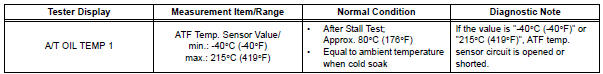
HINT: When DTC P0712 is output and OBD II scan tool or intelligent tester output is 150°C (302°F), there is a short circuit.
When DTC P0713 is output and OBD II scan tool or intelligent tester output is -40°C (-40°F), there is an open circuit.
Measure the resistance between terminal THO1 (THO) and body ground.
HINT: If a circuit related to the ATF temperature sensor becomes open, P0713 is immediately set (in 0.5 second).
When P0713 is set, P0711 cannot be detected.
It is not necessary to inspect the circuit when P0711 is set.
1 CHECK OTHER DTCS OUTPUT (IN ADDITION TO DTC P0711)
(a) Connect the intelligent tester together with the CAN VIM (controller area network vehicle interface module) to the DLC3.
(b) Turn the ignition switch to the ON position and push the OBD II scan tool or the intelligent tester main switch ON.
(c) When you use intelligent tester: Select the item "DIAGNOSIS / ENHANCED OBD II / DTC INFO / CURRENT CODES".
(d) Read the DTCs using the OBD II scan tool or the intelligent tester.
Result 
HINT: If any other codes besides "P0711" are output, perform troubleshooting for those DTCs first.


2 CHECK TRANSMISSION FLUID LEVEL
OK: Automatic transmission fluid level is correct.


REPLACE TRANSMISSION WIRE (ATF TEMPERATURE SENSOR)
 Transmission Fluid Temperature Sensor "A"
DESCRIPTION
The ATF (Automatic Transmission Fluid) temperature sensor converts the fluid
temperature into a
resistance value which is input into the ECM.
The ECM applies a voltage to the te ...
 Turbine Speed Sensor Circuit No Signal
DESCRIPTION
This sensor detects the rotation speed of the input turbine. By comparing the
input turbine speed signal
(NT) with the counter gear speed sensor signal (NC), the ECM detects the sh ...
Other materials:
Inspection
1. INSPECT FRONT DIFFERENTIAL
(a) Using a dial indicator, measure the backlash of one
pinion gear while holding the front differential side
gear toward the case.
Standard backlash:
0.05 - 0.20 mm (0.0020 - 0.0079 in.)
NOTICE:
Do not mount the surface of front differential
case which cont ...
Short to B+ in Side Squib LH Circuit
DTC B0118/46 Short to B+ in Side Squib LH Circuit
DESCRIPTION
The side squib LH circuit consists of the center airbag sensor assembly and
the front seat side airbag
assembly LH (side squib LH).
This circuit instructs the SRS to deploy when deployment conditions are met.
DTC B0118/46 is re ...
Disc cannot be Played/ No Playable Files/ Copyright Protection Error
DTC 63-7D Disc cannot be Played
DTC 63-7E No Playable Files
DTC 63-7F Copyright Protection Error
DESCRIPTION
DTC No.
DTC Detection Condition
Trouble Area
63-7D
An incompatible MP3 / WMA file is used.
Although the file has an extension of &quo ...
