Toyota Sienna Service Manual: Perform zero point calibration of yaw rate and deceleration sensor (when using sst check wire)
NOTICE:
- While obtaining the zero point, do not vibrate the vehicle by tilting, moving or shaking it and keep it in a stationary condition. (Do not turn the ignition switch to the ON position.)
- Be sure to do this on a level surface (with an inclination of less than 1 %).
(a) Procedures for test mode.
(1) Check that the steering wheel is in the straightahead position and move the shift lever to the P position and apply the parking brake.
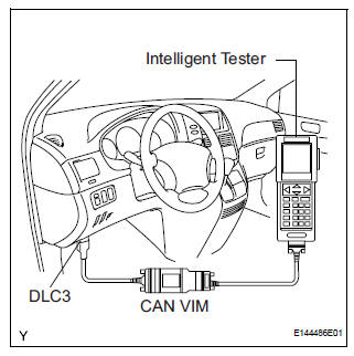
(2) Connect the intelligent tester to the DLC3.
(3) Turn the ignition switch to the ON position.
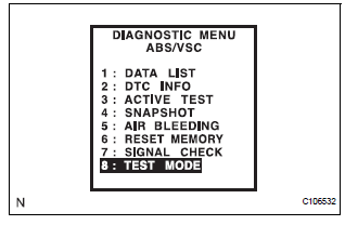
(4) Set the intelligent tester to test mode (select "TEST MODE").
HINT: Refer to the intelligent tester operator's manual for further details.
(b) Obtain the zero point of the yaw rate and deceleration sensor.
(1) Keep the vehicle in the stationary condition on a level surface for 2 seconds or more.
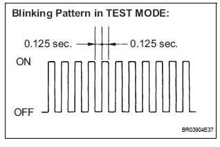
(2) Check that the ABS warning light and VSC warning light blink.
HINT:
- If the ABS warning light and VSC warning light do not blink perform zero point calibration again.
- The zero point calibration is performed only once after the system enters the test mode.
- Calibration cannot be performed again until the stored data is cleared once.
(c) Turn the ignition switch off and disconnect the intelligent tester.
PERFORM ZERO POINT CALIBRATION OF YAW RATE AND DECELERATION SENSOR (WHEN USING SST CHECK WIRE):
NOTICE:
- While obtaining the zero point, do not vibrate the vehicle by tilting, moving or shaking it and keep it in a stationary condition. (Do not turn the ignition switch to the ON position.)
- Be sure to do this on a level surface (with an inclination of less than 1 %).
(a) Clear the zero point calibration.
(1) Turn the ignition switch to the ON position.
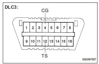
(2) Using SST, connect and disconnect terminals TS and CG of the DLC3 4 times or more within 8 seconds.
SST 09843-18040
(b) Procedures for test mode.
(1) Turn the ignition switch off.
(2) Using SST, connect terminals TS and CG of the DLC3.
SST 09843-18040
(3) Check that the steering wheel is in the straightahead position and move the shift lever to the P position.
(c) Obtain the zero point of the yaw rate and deceleration sensor.
(1) Turn the ignition switch to the ON position.
(2) Keep the vehicle in a stationary condition on a level surface for 2 seconds or more.
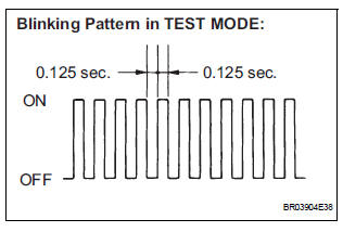
(3) Check that the ABS warning light and VSC light blink (test mode).
HINT:
- If the ABS warning light and VSC warning light do not blink perform zero point calibration again.
- The zero point calibration is performed only once after the system enters the test mode.
- Calibration cannot be performed again until the stored data is cleared once.
(d) Turn the ignition switch off and disconnect the SST from the DLC3.
 Perform zero point calibration of yaw rate and deceleration sensor (when
using intelligent tester)
Perform zero point calibration of yaw rate and deceleration sensor (when
using intelligent tester)
(a) Connect the intelligent tester to the DLC3.
(b) Turn the ignition switch to the ON position.
(c) Operate the intelligent tester to erase the codes
(select "RESET MEMORY").
...

Other materials:
Throttle Actuator Control Throttle Body Range / Performance
DESCRIPTION
The Electronic Throttle Control System (ETCS) is composed of the throttle
actuator, Throttle Position (TP)
sensor, Accelerator Pedal Position (APP) sensor, and ECM. The ECM operates the
throttle actuator to
regulate the throttle valve in response to driver inputs. The TP senso ...
Anti-glare function
Manual anti-glare inside rear view mirror
Reflected light from the headlights of vehicles behind can be reduced
by operating the lever.
Normal position
Anti-glare position
Auto anti-glare inside rear view mirror
Responding to the level of brightness of the headlights of veh ...
Check for intermittent
problems
1. CHECK FOR INTERMITTENT PROBLEMS
HINT:
For use of the intelligent tester only:
Inspect the vehicle's ECM using check mode.
Intermittent problems are easier to detect with an
intelligent tester when the ECM is in check mode. In
check mode, the ECM uses 1 trip detection logic, which
is more ...
