Toyota Sienna Service Manual: Throttle Actuator Control Throttle Body Range / Performance

DESCRIPTION
The Electronic Throttle Control System (ETCS) is composed of the throttle actuator, Throttle Position (TP) sensor, Accelerator Pedal Position (APP) sensor, and ECM. The ECM operates the throttle actuator to regulate the throttle valve in response to driver inputs. The TP sensor detects the opening angle of the throttle valve, and provides the ECM with feedback so that the throttle valve can be appropriately controlled by the ECM.

MONITOR DESCRIPTION
The ECM determines the actual opening angle of the throttle valve from the TP sensor signal. The actual opening angle is compared to the target opening angle commanded by the ECM. If the difference between these two values is outside the standard range, the ECM interprets this as a malfunction in the ETCS. The ECM then illuminates the MIL and sets the DTC.
If the malfunction is not repaired successfully, the DTC is set when the accelerator pedal is quickly released (to close the throttle valve) after the engine speed reaches 5000 rpm by the accelerator pedal being fully depressed (fully open the throttle valve).
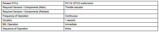
MONITOR STRATEGY
TYPICAL ENABLING CONDITIONS
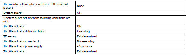
TYPICAL MALFUNCTION THRESHOLDS

FAIL-SAFE
When this DTC, as well as other DTCs relating to ETCS (Electronic Throttle Control System) malfunctions, is set, the ECM enters fail-safe mode. During fail-safe mode, the ECM cuts the current to the throttle actuator off, and the throttle valve is returned to a 6° throttle angle by the return spring. The ECM then adjusts the engine output by controlling the fuel injection (intermittent fuel-cut) and ignition timing, in accordance with the accelerator pedal opening angle, to allow the vehicle to continue at a minimal speed. If the accelerator pedal is depressed slowly, the vehicle can be driven slowly.
Fail-safe mode continues until a pass condition is detected, and the ignition switch is then turned off.
WIRING DIAGRAM
Refer to DTC P2102 (See page ES-331).
INSPECTION PROCEDURE
HINT:
Read freeze frame data using the intelligent tester. The ECM records vehicle and driving condition information as freeze frame data the moment a DTC is stored. When troubleshooting, freeze frame data can be helpful in determining whether the vehicle was running or stopped, whether the engine was warmed up or not, whether the air-fuel ratio was lean or rich, as well as other data recorded at the time of a malfunction.
1 CHECK ANY OTHER DTCS OUTPUT (IN ADDITION TO DTC P2119)
(a) Connect the intelligent tester to the DLC3.
(b) Turn the ignition switch to the ON position.
(c) Turn the tester on.
(d) Select the following menu items: DIAGNOSIS / ENHANCED OBD II / DTC INFO / CURRENT CODES.
(e) Read the DTCs.
Result 
HINT: If any DTCs other than P2119 are output, troubleshoot those DTCs first.


2 CHECK WHETHER DTC OUTPUT RECURS (DTC P2119)
(a) Connect the intelligent tester to the DLC3.
(b) Turn the ignition switch to the ON position.
(c) Turn the tester on.
(d) Clear the DTCs (See page ES-39).
(e) Allow the engine to idle for 15 seconds.
| CAUTION: Perform the procedures "A" and "B" below with great care. Failure to do so may result in the vehicle unexpectedly rolling away. |
(f) Securely apply the parking brake and move the gear selector lever to the D position (Procedure "A").
(g) While depressing the brake pedal securely, fully depress the accelerator pedal for 5 seconds (Procedure "B").
(h) Select the following menu items on the tester: DIAGNOSIS / ENHANCED OBD II / DTC INFO / CURRENT CODES.
(i) Read the DTCs.
HINT: The voltage output of the throttle position sensor can be checked during procedure "B" using the intelligent tester.
Variations in the voltage output indicate that the throttle actuator is in operation. To check the voltage output using the intelligent tester, select the following menu items: DIAGNOSIS / ENHANCED OBD II / DATA LIST / PRIMARY / THROTTLE POS #1.
OK: No DTC output.

CHECK FOR INTERMITTENT PROBLEMS
 Throttle Actuator Control Motor Current Range / Performance
DESCRIPTION
The ETCS (Electronic Throttle Control System) has a dedicated power supply
circuit. The voltage (+BM)
is monitored and when it is low (less than 4 V), the ECM determines that there ...
 Throttle / Pedal Position Sensor
HINT:
These DTCs relate to the Accelerator Pedal Position (APP) sensor.
DESCRIPTION
HINT:
This ETCS (Electronic Throttle Control System) does not use a throttle cable.
The Accelerator Pedal ...
Other materials:
Road test
1. PROBLEM SYMPTOM CONFIRMATION
Inspect the SET function.
Turn the cruise control main switch on.
Drive at the required speed between 40 km/h
(25 mph) and 200 km/h (125 mph).
Push the cruise control main switch to -
(COAST)/SET.
After releasing t ...
Diagnosis system
1. CHECK DLC3
The vehicle's ECU uses ISO 15765-4 for
communication protocol. The terminal arrangement
of the DLC3 complies with SAE J1962 and matches
the ISO 15765-4 format
NOTICE:
*: Before measuring the resistance, leave the
vehicle as is for at least 1 minute and do not
oper ...
Removal
HINT:
Use the same procedures for the RH side and LH side.
The procedures listed below are for the LH side.
1. PRECAUTION
CAUTION: Be sure to read "PRECAUTION" thoroughly before
servicing.
2. DISCONNECT CABLE FROM NEGATIVE BATTERY
TERMINAL
NOTICE:
Wait for 90 seconds ...
