Toyota Sienna Service Manual: Pressure Control Solenoid "A" Electrical (Shift Solenoid Valve SL1)
DESCRIPTION
Shifting from 1st to 5th is performed in combination with "ON" and "OFF"
operation of the shift solenoid
valves SL1, SL2, SL3, S4 and SR which are controlled by the ECM. If an open or
short circuit occurs in
either of the shift solenoid valves, the ECM controls the remaining normal shift
solenoid valves to allow
the vehicle to be operated smoothly (Fail safe function).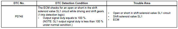
MONITOR DESCRIPTION
The ECM commands gear shifts by turning the shift solenoid valves "ON/OFF". When there is an open or short circuit in any shift solenoid valve circuit, the ECM detects the problem and illuminates the MIL and stores the DTC. And the ECM performs the fail-safe function and turns the other normal shift solenoid valves "ON/OFF" (In case of an open or short circuit, the ECM stops sending current to the circuit.) (See page AX-30).
MONITOR STRATEGY
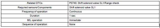
TYPICAL ENABLING CONDITIONS
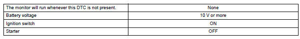
TYPICAL MALFUNCTION THRESHOLDS

COMPONENT OPERATING RANGE

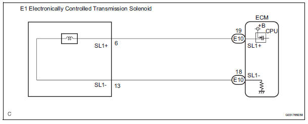
WIRING DIAGRAM
INSPECTION PROCEDURE
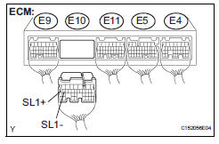
1 INSPECT TRANSMISSION WIRE (SL1)
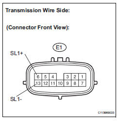
(a) Disconnect the transmission wire connector from the transaxle.
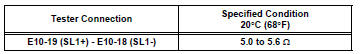
(b) Measure the resistance according to the value(s) in the table below.
Standard resistance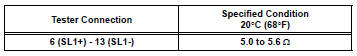
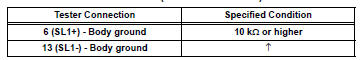
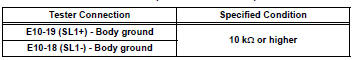
(c) Measure the resistance according to the value(s) in the table below.
Standard resistance (Check for short)


2 CHECK HARNESS AND CONNECTOR (TRANSMISSION WIRE - ECM)
(a) Connect the transmission wire connector to the transaxle.
(b) Disconnect the connector from the ECM.
(c) Measure the resistance according to the value(s) in the table below.
Standard resistance
(d) Measure the resistance according to the value(s) in the table below.
Standard resistance (Check for short)

REPLACE ECM
INSPECT SHIFT SOLENOID VALVE SL1
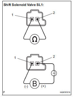
(a) Remove the shift solenoid valve SL1.
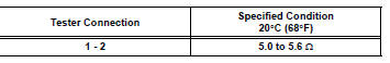
(b) Measure the resistance according to the value(s) in the table below.
Standard resistance
(c) Connect the positive (+) lead with a 21 W bulb to terminal 2 and the negative (-) lead to terminal 1 of the solenoid valve connector, then check the movement of the valve.
OK: The solenoid makes an operating sound.

REPAIR OR REPLACE TRANSMISSION WIRE
 Pressure Control Solenoid "A" Performance (Shift Solenoid
Valve SL1)
Pressure Control Solenoid "A" Performance (Shift Solenoid
Valve SL1)
SYSTEM DESCRIPTION
The ECM uses signals from the vehicle speed sensor to
detect the actual gear position (1st, 2nd, 3rd, 4th
or 5th gear).
Then the ECM compares the actual gear with the shi ...
 Shift Solenoid "D" Performance (Shift Solenoid
Valve S4)
Shift Solenoid "D" Performance (Shift Solenoid
Valve S4)
SYSTEM DESCRIPTION
The ECM uses signals from the vehicle speed sensor to detect the actual gear
position (1st, 2nd, 3rd, 4th
or 5th gear).
Then the ECM compares the actual gear with the shi ...
Other materials:
Open in Stop Light Switch Circuit
DTC C1249/49 Open in Stop Light Switch Circuit
DESCRIPTION
This skid control ECU inputs the stop light switch signal and detects the
status of brake operation.
The skid control ECU has an open detection circuit. If an open in the stop light
switch input line or GND
side stop light circuit ...
ECU Power Source Circuit
DESCRIPTION
This is the power source for the tire pressure warning ECU.
WIRING DIAGRAM
INSPECTION PROCEDURE
NOTICE:
When replacing the tire pressure warning ECU, read the transmitter IDs
stored in the old ECU
using the intelligent tester and write them down before removal.
It is neces ...
Checking and replacing
fuses
If any of the electrical components do not operate, a fuse may
have blown. If this happens, check and replace the fuses as necessary.
Turn the engine switch to the “LOCK” position (vehicles without a
smart key system) or off (vehicles with a smart key system).
Open the fuse box cover.
...
