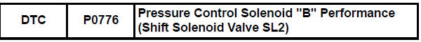
Toyota Sienna Service Manual: Pressure Control Solenoid "B" Performance (Shift Solenoid Valve SL2)
SYSTEM DESCRIPTION
The ECM uses signals from the vehicle speed sensor to detect the actual gear position (1st, 2nd, 3rd, 4th or 5th gear).
Then the ECM compares the actual gear with the shift schedule in the ECM memory
to detect mechanical
problems of the shift solenoid valves, valve body or automatic transaxle
(clutch, brake or gear etc.).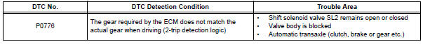
MONITOR DESCRIPTION
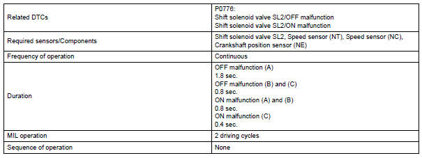
The ECM commands gear shifts by turning the shift solenoid valves "ON/OFF". According to the input shaft revolution, intermediate (counter) shaft revolution and output shaft revolution, the ECM detects the actual gear position (1st, 2nd, 3rd, 4th or 5th gear position). When the gear position commanded by the ECM and the actual gear position are not the same, the ECM illuminates the MIL and stores the DTC.
MONITOR STRATEGY
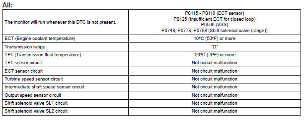
TYPICAL ENABLING CONDITIONS
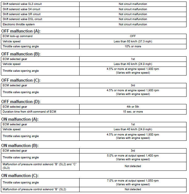
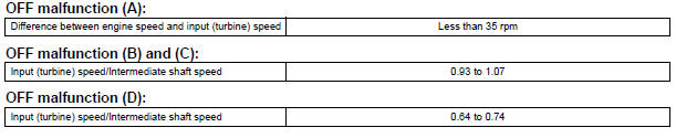
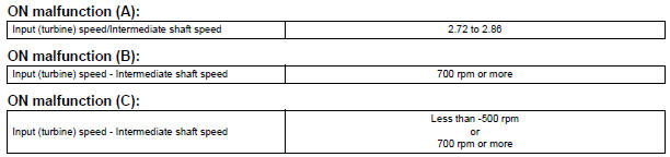
TYPICAL MALFUNCTION THRESHOLDS
Either of the following conditions is met: OFF malfunction (A), (B), (C) and (D), or ON malfunction (A), (B) and (C)
INSPECTION PROCEDURE
HINT: Using the intelligent tester to perform ACTIVE TEST allows relays, VSVs, actuators and other items to be operated without removing any parts. This non-intrusive functional inspection can be very useful because intermittent operation may be discovered before parts or wiring is disturbed. Performing ACTIVE TEST early in troubleshooting is one way to save diagnostic time. DATA LIST information can be displayed while performing ACTIVE TEST.
1. PERFORM ACTIVE TEST
(a) Warm up the engine.
(b) Turn the ignition switch off.
(c) Connect the intelligent tester together with the CAN VIM (controller area network vehicle interface module) to the DLC3.
(d) Turn the ignition switch to the ON position.
(e) Turn on the tester.
(f) Select the item "DIAGNOSIS / ENHANCED OBD II / ACTIVE TEST / SHIFT".
(g) According to the display on the tester, perform the "ACTIVE TEST".
HINT: While driving, the shift position can be forcibly changed with the intelligent tester.
Comparing the shift position commanded by the ACTIVE TEST with the actual shift
position enables you
to confirm the problem (See page AX-30).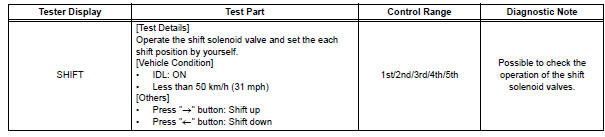
HINT:
- This test can be conducted when the vehicle speed is 50 km/h (31 mph) or less.
- The shift position commanded by the ECM is shown in the DATA LIST/SHIFT display on the intelligent tester.
1 CHECK OTHER DTCS OUTPUT (IN ADDITION TO DTC P0776)
(a) Connect the intelligent tester together with the CAN VIM (controller area network vehicle interface module) to the DLC3.
(b) Turn the ignition switch to the ON position and turn the OBD II scan tool or the intelligent tester main switch ON.
(c) When you use intelligent tester:
Select the item "DIAGNOSIS / ENHANCED OBD II / DTC INFO / CURRENT CODES".
(d) Read the DTCs using the OBD II scan tool or the intelligent tester.
Result
HINT: If any other codes besides "P0776" are output, perform the troubleshooting for those DTCs first.


2 INSPECT SHIFT SOLENOID VALVE SL2
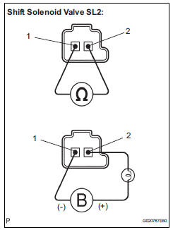
(a) Remove the shift solenoid valve SL2.
(b) Measure the resistance according to the value(s) in the table below.
Standard resistance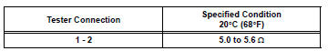
(c) Connect the positive (+) lead with a 21 W bulb to terminal 2 and the negative (-) lead to terminal 1 of the solenoid valve connector, then check the movement of the valve.
OK: The solenoid makes an operating sound.

3 INSPECT TRANSMISSION VALVE BODY ASSEMBLY
OK: There are no foreign objects on each valve and they operate smoothly.

4 INSPECT TORQUE CONVERTER CLUTCH ASSEMBLY
OK: The torque converter clutch operates normally.

REPAIR OR REPLACE AUTOMATIC TRANSAXLE ASSEMBLY
 Shift Solenoid "E" Performance (Shift Solenoid
Valve SR)
Shift Solenoid "E" Performance (Shift Solenoid
Valve SR)
SYSTEM DESCRIPTION
The ECM uses signals from the vehicle speed sensor to detect the actual gear
position (1st, 2nd, 3rd, 4th
or 5th gear).
Then the ECM compares the actual gear with the shi ...
 Pressure Control Solenoid "B" Electrical (Shift
Solenoid Valve SL2)
Pressure Control Solenoid "B" Electrical (Shift
Solenoid Valve SL2)
DESCRIPTION
Shifting from 1st to 5th is performed in combination with "ON" and "OFF"
operation of the shift solenoid
valves SL1, SL2, SL3, S4 and SR which are controlled by ...
Other materials:
On-vehicle inspection
1. INSPECT STEERING PAD (VEHICLE NOT INVOLVED IN COLLISION)
Perform a diagnostic system check.
With the steering pad installed on the vehicle,
perform a visual check. If there are any defects as
mentioned below, replace the steering pad with a
new one:
Cuts, minute cracks or marked ...
Summary of functions
Dynamic radar cruise control supplements conventional cruise control
with a vehicle-to-vehicle distance control. In vehicle-to-vehicle distance
control mode, the vehicle automatically accelerates or decelerates
in order to maintain a set following distance from vehicles ahead.
Multi-infor ...
Unlocking and locking the doors from the inside
Door lock switch
Locks all the doors
Unlocks all the doors
Inside lock button
Locks the door
Unlocks the door
The front doors can be opened
by pulling the inside handle
even if the lock buttons are in
the lock position. ...
