Toyota Sienna Service Manual: Purpose of readiness tests
- The On-Board Diagnostic (OBD II) system is
designed to monitor the performance of emissionrelated
components, and indicate any detected
abnormalities with DTCs (Diagnostic Trouble Codes).
Since various components need to be monitored in different driving conditions, the OBD II system is designed to run separate monitoring programs called Readiness Monitors.
- The intelligent tester's software must be version 9.0 or newer to view the Readiness Monitor status. To view the status, select the following menu items: DIAGNOSIS / ENHANCED OBD II / MONITOR INFO / MONITOR STATUS.
- When the Readiness Monitor status reads COMPL (complete), the necessary conditions have been met for running the performance tests for that Readiness Monitor.
- A generic OBD II scan tool can also be used to view the Readiness Monitor status.
HINT:
Many Inspection and Maintenance (I/M) programs require a vehicle's Readiness Monitor status to show COMPL before beginning emission tests.
The Readiness Monitor will be reset to INCMPL (incomplete) if:
- The ECM has lost battery power or broken a fuse.
- DTCs have been cleared.
- The conditions for running the Readiness Monitor have not been met.
If the Readiness Monitor status shows INCMPL, follow the appropriate Readiness Monitor Drive Pattern to change the status to COMPL.
| CAUTION: Strictly observe posted speed limits, traffic laws, and road conditions when performing these drive patterns. |
| NOTICE: These drive patterns represent the fastest method of satisfying all conditions necessary to achieve complete status for each specific Readiness Monitor. In the event of a drive pattern being interrupted (possibly due to factors such as traffic conditions), the drive pattern can be resumed. In most cases, the Readiness Monitor will still achieve complete status upon completion of the drive pattern. To ensure completion of the Readiness Monitors, avoid sudden changes in vehicle load and speed (driving up and down hills and/or sudden acceleration). |
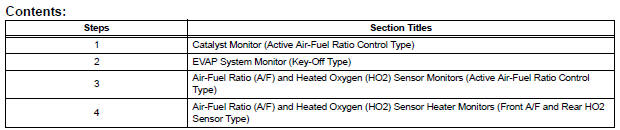

 Catalyst monitor (active air-fuel ratio control
type)
Catalyst monitor (active air-fuel ratio control
type)
(a) Preconditions
The monitor will not run unless:
The MIL is OFF.
(b) Drive Pattern
(1) Connect an intelligent tester.
(2) Turn the ignition switch to the ON position.
(3) Turn the ...
Other materials:
Command list
Some recognizable voice commands and their actions are shown
below as examples.
Basic
Command
Action
“Help”
Prompts voice guidance to offer examples of commands
or operation methods
“Go Back”
Returns to the previous screen
Phone
...
Axle
SST
RECOMMENDED TOOLS
HINT:
Trox is a registered trademark of Trxtron Inc.
EQUIPMENT
...
Installation
1. INSTALL NO.1 NAVIGATION BRACKET
Install the No.1 navigation bracket with the 4
screws.
2. INSTALL NO.2 NAVIGATION BRACKET
Install the No.2 navigation bracket with the 4
screws.
3. INSTALL INSTRUMENT CLUSTER FINISH PANEL UPPER
Install the instrum ...
