Toyota Sienna Service Manual: Installation
HINT: Install the RH side by the same procedure as the LH side.
1. INSTALL REAR DISC BRAKE CYLINDER MOUNTING LH
(a) Install the rear disc brake cylinder mounting LH with the 2 bolts.
Torque: 88 N*m (900 kgf*cm, 65 ft.*lbf)
2. INSTALL REAR DISC BRAKE PAD SUPPORT PLATE
(a) Install the rear disc brake pad support plate (No. 1) and rear disc brake pad support plate (No. 2) to the rear disc brake cylinder mounting LH.
3. INSTALL REAR DISC BRAKE ANTI SQUEAL SHIM KIT
NOTICE: If necessary, replace the anti squeal shim kit when replacing the brake pad.
(a) Apply disc brake grease to each anti squeal shim No. 1.
(b) Install anti squeal shims No. 1 and anti squeal shim No. 2 on each pad.
4. INSTALL DISC BRAKE PAD KIT REAR (PAD ONLY)
(a) Install the brake pad kit rear to the rear disc brake cylinder mounting LH.
NOTICE: There should be no oil or grease on the friction surfaces of the pads and the disc.
5. INSTALL DISC BRAKE CYLINDER ASSEMBLY REAR LH
(a) Install the disc brake cylinder assembly rear LH with the 2 bolts.
Torque: 34 N*m (350 kgf*cm, 25 ft.*lbf)
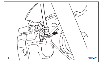
6. CONNECT REAR LH FLEXIBLE HOSE

(a) Using SST, Install the rear brake flexible hose.
SST 09023-12701 Torque: 23 N*m (235 kgf*cm, 17 ft.*lbf)
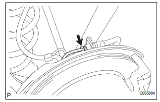
7. CONNECT REAR BRAKE TUBE NO.4
(a) Install the clip and connect the rear brake flexible hose.

(b) Using SST and a spanner, connect the rear brake tube No. 4.
SST 09023-00101 Torque: 15 N*m (155 kgf*cm, 11 ft.*lbf)
8. FILL RESERVOIR WITH BRAKE FLUID (See page BR- 3)
9. BLEED BRAKE MASTER CYLINDER (See page BR-3)
10. BLEED BRAKE LINE (See page BR-4)
11. BLEED BRAKE ACTUATOR (w/ VSC) (See page BR- 4)
12. CHECK FLUID LEVEL IN RESERVOIR (See page BR- 7)
13. CHECK BRAKE FLUID LEAKAGE
14. INSTALL REAR WHEEL Torque: 103 N*m (1,050 kgf*cm, 76 ft.*lbf)
 Reassembly
1. INSTALL REAR DISC
(a) Aligning the matchmarks, install the rear disc.
HINT:
Select the installation position where the disc has
the minimum runout.
2. INSPECT DISC RUNOUT
(a) Temporarily ...
 Rear drum brake
Components
...
Other materials:
Hazard warning switch
INSPECTION
1. HAZARD WARNING SIGNAL SWITCH ASSEMBLY
Check that there is resistance between the
terminals at each switch position as shown in the
chart.
Resistance
Inspect illumination operation.
Connect the positive (+) lead from the battery
to the termina ...
Problem symptoms table
HINT:
Use the table below to help determine the cause of the
problem symptom. The potential causes of the symptoms are
listed in order of probability in the "Suspected Area" column
of the table. Check each symptom by checking the suspected
areas in the order they are listed. Replace p ...
Short in Front Pretensioner Squib RH Circuit
DTC B0130/63 Short in Front Pretensioner Squib RH Circuit
DESCRIPTION
The front pretensioner squib RH circuit consists of the center airbag sensor
assembly and the front seat
outer belt assembly RH.
This circuit instructs the SRS to deploy when deployment conditions are met.
DTC B0130/63 ...
