Toyota Sienna Service Manual: Throttle Actuator Control System
DESCRIPTION
The throttle actuator is operated by the ECM, and opens and closes the throttle valve using the gears.
The opening angle of the throttle valve is detected by the Throttle Position (TP) sensor, which is mounted on the throttle body. The TP sensor provides feedback to the ECM so that it can control the throttle actuator and the throttle valve appropriately in response to driver inputs
HINT:
This ETCS (Electronic Throttle Control System) does not use a throttle cable.
MONITOR DESCRIPTION
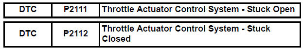
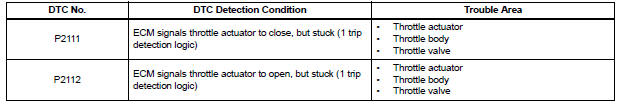
The ECM determines that there is a malfunction in the ETCS when the throttle valve remains at the fixed angle despite a high drive current from the ECM. The ECM illuminates the MIL and sets a DTC.
If the malfunction is not repaired successfully, a DTC is set when the accelerator pedal is fully depressed and released quickly (to fully open and close the throttle valve) after the engine is next started.
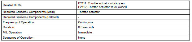
MONITOR STRATEGY
TYPICAL ENABLING CONDITIONS
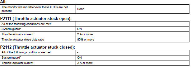
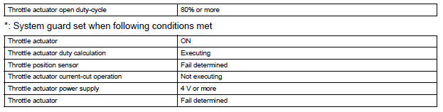
TYPICAL MALFUNCTION THRESHOLDS
FAIL-SAFE
When either of these DTCs, as well as other DTCs relating to ETCS (Electronic Throttle Control System) malfunctions, is set, the ECM enters fail-safe mode. During fail-safe mode, the ECM cuts the current to the throttle actuator off, and the throttle valve is returned to a 6° throttle angle by the return spring. The ECM then adjusts the engine output by controlling the fuel injection (intermittent fuel-cut) and ignition timing, in accordance with the accelerator pedal opening angle, to allow the vehicle to continue at a minimal speed.
If the accelerator pedal is depressed slowly, the vehicle can be driven slowly.
Fail-safe mode continues until a pass condition is detected, and the ignition switch is then turned off.
WIRING DIAGRAM
Refer to DTC P2102 (See page ES-331).
INSPECTION PROCEDURE
HINT:
Read freeze frame data using the intelligent tester. The ECM records vehicle and driving condition information as freeze frame data the moment a DTC is stored. When troubleshooting, freeze frame data can be helpful in determining whether the vehicle was running or stopped, whether the engine was warmed up or not, whether the air-fuel ratio was lean or rich, as well as other data recorded at the time of a malfunction.
1 CHECK ANY OTHER DTCS OUTPUT (IN ADDITION TO DTC P2111 OR P2112)
(a) Connect the intelligent tester to the DLC3.
(b) Turn the ignition switch to the ON position.
(c) Turn the tester on.
(d) Select the following menu items: DIAGNOSIS / ENHANCED OBD II / DTC INFO / CURRENT CODES.
(e) Read the DTCs.
Result 
HINT: If any DTCs other than P2111 or P2112 are output, troubleshoot those DTCs first.


2 INSPECT THROTTLE BODY (VISUALLY CHECK THROTTLE VALVE)
(a) Check for contamination between the throttle valve and the housing. If necessary, clean the throttle body. And check that the throttle valve moves smoothly.
OK: Throttle valve is not contaminated with foreign objects and moves smoothly.

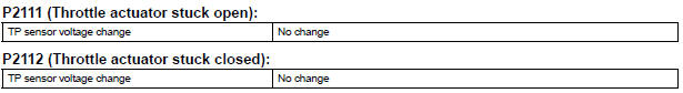
3 CHECK WHETHER DTC OUTPUT RECURS (DTC P2111 OR P2112)
(a) Connect the intelligent tester to the DLC3.
(b) Turn the ignition switch to the ON position.
(c) Turn the tester on.
(d) Clear the DTCs (See page ES-39).
(e) Start the engine, and fully depress and release the accelerator pedal quickly (to fully open and close the throttle valve).
(f) Select the following menu items: DIAGNOSIS / ENHANCED OBD II / DTC INFO / CURRENT CODES.
(g) Read the DTCs.
Result 


CHECK FOR INTERMITTENT PROBLEMS
 Throttle Actuator Control Motor Circuit
DESCRIPTION
The throttle actuator is operated by the ECM and opens and closes the
throttle valve using gears.
The opening angle of the throttle valve is detected by the Throttle Position
( ...
 Throttle Actuator Control Motor Current Range / Performance
DESCRIPTION
The ETCS (Electronic Throttle Control System) has a dedicated power supply
circuit. The voltage (+BM)
is monitored and when it is low (less than 4 V), the ECM determines that there ...
Other materials:
Disc cannot be Played/ No Playable Files/ Copyright Protection Error/ Disc
cannot be Played/ No Playable Files/ Copyright Protection Error
DTC 62-7D Disc cannot be Played
DTC 62-7E No Playable Files
DTC 62-7F Copyright Protection Error
DTC 63-7D Disc cannot be Played
DTC 63-7E No Playable Files
DTC 63-7F Copyright Protection Error
DESCRIPTION
INSPECTION PROCEDURE
HINT:
After the inspection is completed, clear the DTCs.
1 ...
System description
1. GENERAL
The dynamic laser cruise control system has two
cruise control modes: the constant speed control
mode and vehicle-to-vehicle distance control mode.
The vehicle-to-vehicle distance control mode is
always selected when starting the dynamic laser
cruise control ...
Disassembly
1. REMOVE REAR SEAT LEG COVER LH
Remove the 2 screws and seat leg cover.
2. REMOVE REAR SEAT LEG COVER RH
Remove the 2 screws and seat leg cover.
3. REMOVE REAR SEAT LEG SIDE COVER LH
Remove the 2 screws and seat leg side cover.
4. REMOVE LH SEAT REAR SEAT LOCK ...
