Toyota Sienna Service Manual: Rear Occupant Classification Sensor LH Collision Detection
DTC B1787 Rear Occupant Classification Sensor LH Collision Detection
DESCRIPTION
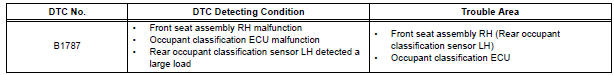
DTC B1787 is output when the occupant classification ECU receives a collision detection signal sent by the rear occupant classification sensor LH if an accident occurs.
DTC B1787 is also output when the front seat assembly RH is subjected to a strong impact, even if an actual accident does not occur.
However, when the occupant classification ECU outputs a collision detection signal, even if the vehicle is not in a collision, DTC B1787 can be cleared by "Zero point calibration" and "Sensitivity check".
Therefore, if DTC B1787 is output, first perform "Zero point calibration" and "Sensitivity check".
WIRING DIAGRAM
INSPECTION PROCEDURE
1 PERFORM ZERO POINT CALIBRATION
- Connect the intelligent tester to the DLC3.
- Turn the ignition switch to the ON position.
- Using the intelligent tester, perform "Zero point calibration".
OK: "COMPLETED" is displayed.
2 PERFORM SENSITIVITY CHECK
- Using the intelligent tester, perform "Sensitivity check".
Standard value: 27 to 33 kg (59.52 to 72.75 lb)
3 CHECK DTC
- Turn the ignition switch to the ON position.
- Clear the DTCs stored in the memory
HINT: First clear DTCs stored in the occupant classification ECU and then in the center airbag sensor assembly. - Turn the ignition switch to the LOCK position.
- Turn the ignition switch to the ON position.
- Check the DTCs.
OK: DTC B1787 is not output.
HINT: Codes other than DTC B1787 may be output at this time, but they are not related to this check.
4 REPLACE FRONT SEAT ASSEMBLY RH
- Turn the ignition switch to the LOCK position.
- Disconnect the negative (-) terminal cable from the battery, and wait for at least 90 seconds.
- Replace the front seat assembly RH ( for flat type, SE-48 for manual seat, SE-58 for power seat).
HINT: Perform the inspection using parts from a normal vehicle if possible.
5 PERFORM ZERO POINT CALIBRATION
- Connect the negative (-) terminal cable to the battery.
- Connect the intelligent tester to the DLC3.
- Turn the ignition switch to the ON position.
- Using the intelligent tester, perform "Zero point calibration".
OK: "COMPLETED" is displayed.
6 PERFORM SENSITIVITY CHECK
- Using the intelligent tester, perform "Sensitivity check".
Standard value: 27 to 33 kg (59.52 to 72.75 lb)
7 CHECK DTC
- Turn the ignition switch to the ON position.
- Clear the DTCs stored in the memory.
HINT: First clear DTCs stored in the occupant classification ECU and then in the center airbag sensor assembly.
- Turn the ignition switch to the LOCK position.
- Turn the ignition switch to the ON position.
- Check the DTCs.
OK: DTC B1787 is not output.
HINT: Codes other than DTC B1787 may be output at this time, but they are not related to this check.
8 REPLACE OCCUPANT CLASSIFICATION ECU
- Turn the ignition switch to the LOCK position.
- Disconnect the negative (-) terminal cable from the battery, and wait for at least 90 seconds.
- Replace the occupant classification ECU.
9 PERFORM ZERO POINT CALIBRATION
- Connect the negative (-) terminal cable to the battery.
- Connect the intelligent tester to the DLC3.
- Turn the ignition switch to the ON position.
- Using the intelligent tester, perform "Zero point calibration".
OK: "COMPLETED" is displayed.
10 PERFORM SENSITIVITY CHECK
- Using the intelligent tester, perform "Sensitivity check".
Standard value: 27 to 33 kg (59.52 to 72.75 lb)
END
 Front Occupant Classification Sensor RH Collision
Detection
Front Occupant Classification Sensor RH Collision
Detection
DTC B1786 Front Occupant Classification Sensor RH Collision
Detection
DESCRIPTION
DTC B1786 is output when the occupant classification ECU receives a collision
detection signal sent by
the front ...
 Rear Occupant Classification Sensor RH Collision
Detection
Rear Occupant Classification Sensor RH Collision
Detection
DTC B1788 Rear Occupant Classification Sensor RH Collision
Detection
DESCRIPTION
DTC B1788 is output when the occupant classification ECU receives a collision
detection signal sent by
the rear o ...
Other materials:
Rear washer motor
ON-VEHICLE INSPECTION
1. INSPECT REAR WASHER MOTOR
Pour the water into the washer jar with the rear
washer motor assembly installed to the washer jar
assembly.
Connect the battery (+) to the terminal 1 of the rear
washer motor assembly, the battery (-) to the
terminal ...
If you have a flat tire
(vehicles with
run-flat tires)
Your vehicle is not equipped with a spare tire, but instead you
can continue driving the vehicle with run-flat tires even if any
tire goes flat.
In this case, slow down and drive with extra caution.
Run-flat tires (A “RFT” or “DSST” mark is molded on the sidewall)
Take your vehicle to ...
Center Airbag Sensor Assembly Malfunction
DTC B1100/31 Center Airbag Sensor Assembly Malfunction
DESCRIPTION
The center airbag sensor assembly consists of the center airbag sensor
assembly, safing sensor, drive
circuit, diagnosis circuit and ignition control, etc.
It receives signals from the airbag sensor, judges whether or not the ...
