Toyota Sienna Service Manual: Reassembly
1. INSTALL LIGHT CONTROL ECU (DISCHARGE HEADLIGHT)
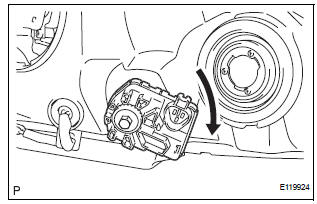
- Install a new headlight leveling motor base packing.
- Install the headlight leveling motor assembly as shown in the illustration.
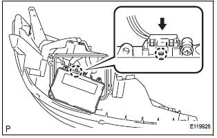
- Connect the connector with the claw
- Install the light control ECU with the 2 screws.
- Install a new headlight gasket.
- Install the headlight cover with the 4 screws.
2. INSTALL FRONT SIDE MARKER LIGHT BULB
- Install the side marker light bulb to the side marker light socket
- Turn in the direction indicated by the arrow and install the side marker light bulb and side marker light socket as a unit.
3. INSTALL FRONT TURN SIGNAL LIGHT BULB
- Install the front turn signal light bulb to the front turn signal light socket.
- Turn in the direction indicated by the arrow and install the front turn signal light bulb and front turn signal light socket as a unit.
4. INSTALL NO. 2 HEADLIGHT BULB
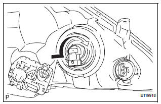
- Turn in the direction indicated by the arrow and install the No.2 headlight bulb.
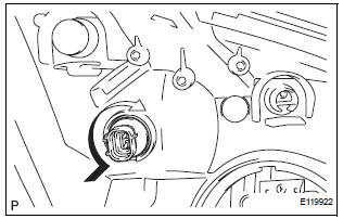
5. INSTALL DISCHARGE HEADLIGHT BULB (DISCHARGE HEADLIGHT)
- Install the discharge headlight bulb with the set spring as shown in the illustration.
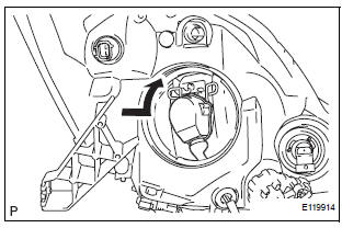
- Turn in the direction indicated by the arrow and install the socket.
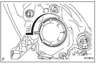
- Turn in the direction indicated by the arrow and install the headlight socket cover.
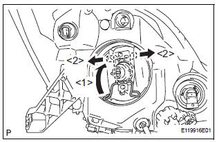
6. INSTALL NO. 1 HEADLIGHT BULB (HALOGEN HEADLIGHT)
- Turn in the direction indicated by the arrow and install the No.1 headlight bulb.
 Adjustment
1. VEHICLE PREPARATION FOR HEADLIGHT AIMING
ADJUSTMENT
Prepare the vehicle:
Ensure there is no damage or deformation to the
body around the headlights.
Fill the fuel t ...
 Installation
1. INSTALL HEADLIGHT ASSEMBLY
Connect the connectors.
Install the headlight assembly with the bolt and 3
screws.
2. INSTALL FRONT BUMPER ASSEMBLY
3. CONNECT CABLE TO NEGATI ...
Other materials:
Removal
1. Disconnect cable from negative battery
terminal
2. REMOVE STEERING COLUMN COVER LOWER
(A) insert the key into the ignition key cylinder and
release the steering lock.
(B) turn the steering wheel clockwise to gain access to
the screw and remove the screw.
(c) Turn the steering whe ...
DTC check / clear
1. DTC CHECK
Connect the intelligent tester to the DLC3.
Connect the intelligent tester to the Controller
Area Network Vehicle Interface Module (CAN
VIM). Then connect the CAN VIM to the Data
Link Connector 3 (DLC3).
Turn the ignition switch to the ON posi ...
Adjustment
1. VEHICLE PREPARATION FOR HEADLIGHT AIMING
ADJUSTMENT
Prepare the vehicle:
Ensure there is no damage or deformation to the
body around the headlights.
Fill the fuel tank.
Make sure that the oil is filled to the specified
level.
Make sure that the c ...
