Toyota Sienna Service Manual: Display does not Dim when Light Control Switch is Turned ON
INSPECTION PROCEDURE
1 CHECK IMAGE QUALITY SETTING
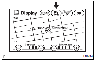
- Enter the display adjustment screen by pressing the "DISPLAY" switch.
- Turn the light control switch to the TAIL position.
- Check if "DAY MODE" on the display adjustment is ON.
OK: "DAY MODE" is ON.
TURN "DAY MODE" SETTING OFF
2 CHECK VEHICLE SIGNAL (DISPLAY CHECK MODE)
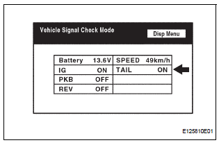
- Enter the "Display Check" mode (Vehicle Signal Check).
- Check that the display changes between ON and OFF according to the light control switch operation.
OK

HINT: The display is updated once per second. It is normal for the display to lag behind the actual switch operation.
REPLACE RADIO AND NAVIGATION ASSEMBLY
 Illumination for Panel Switch does not Come on with Tail Switch ON
INSPECTION PROCEDURE
1 CHECK VEHICLE SIGNAL (DISPLAY CHECK MODE)
Enter the "Display Check" mode (Vehicle Signal Check Mode).
Check that the display changes between ON and OF ...
 Panel Switches do not Function
INSPECTION PROCEDURE
1 CHECK PANEL SWITCH
Check for foreign matter around the switches that might
prevent operation.
OK:
No foreign matter is found
2 CHECK PANEL SWITCH (DISPLAY CHECK MODE ...
Other materials:
Air Mix Damper Control Servo Motor Circuit (Passenger Side)
DESCRIPTION
The air mix control servo motor (air mix damper servo sub-assembly) is
controlled by the A/C amplifier.
The air mix control servo motor moves the air mix damper by rotating (normal,
reverse) with electrical
power from the A/C amplifier.
This adjusts the mix ratio of the air t ...
Reassembly
1. INSTALL OVERDRIVE DIRECT CLUTCH O-RING
(a) Coat an O-ring with ATF, and install it to the direct
clutch drum.
NOTICE:
Make sure that the O-ring is not twisted or
pinched when it is installed.
2. INSTALL OVERDRIVE DIRECT CLUTCH DRUM SUBASSEMBLY
(a) Coat the direct clutch drum with A ...
Sensor detection display, obstacle distance
Distance display
Sensors that detect an obstacle will illuminate continuously or blink.
*1: The images may differ from that shown in the illustrations.
*2: Multi-information display
*3: Audio system screen
Buzzer operation and distance to an obstacle
A buzzer sounds when the sensors are o ...
