Toyota Sienna Service Manual: Engine Coolant Temperature / Intake Air Temperature Correlation
DESCRIPTION
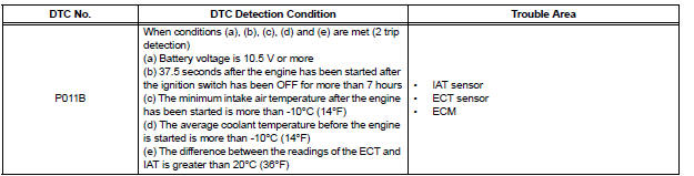
The ECM calculates the difference between the readings of the coolant temperature sensor and intake air temperature sensor. If the difference is greater than 20°C (68°F), the ECM will judge this as a malfunction and will set this DTC.
HINT:
- Waiting is required to prevent the temperature of the engine from affecting the readings. If the engine has been operated recently, it will not be possible to accurately compare the readings.
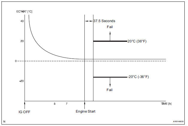
- For diagnosis, in order to duplicate the detection conditions of the DTC, it is necessary to park the vehicle for 7 hours. Parking the vehicle for 7 hours ensures that the actual temperature of the ECT and IAT are very similar. When the vehicle has been parked for less than 7 hours, differences in the readings may exist, this does not necessarily indicate a fault.
MONITOR STRATEGY
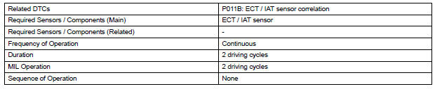
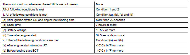
TYPICAL ENABLING CONDITIONS
TYPICAL MALFUNCTION THRESHOLDS

INSPECTION PROCEDURE
1 CHECK ANY OTHER DTCS OUTPUT (IN ADDITION P011B)
(a) Connect the intelligent tester to the DLC3.
(b) Turn the ignition switch to the ON position.
(c) Turn the tester on.
(d) Enter the following menus: DIAGNOSIS / ENHANCED OBD ll / DTC INFO / CURRENT CODES.
(e) Read the DTCs.
Result 

HINT:
If any DTCs other than P011B are output, troubleshoot those DTCs first.
2 READ VALUE OF INTELLIGENT TESTER (INTAKE AIR TEMPERATURE)
(a) Leave the vehicle for 7 hours or more.
HINT:
It is necessary leave the vehicle for 7 hours or more to allow conditions similar to the DTC detection conditions.
(b) Connect the intelligent tester to the DLC3.
(c) Turn the ignition switch to the ON position.
(d) Turn the tester ON.
(e) Enter the following menus: DIAGNOSIS / ENHANCED OBD ll / DATA LIST / PRIMARY / INTAKE AIR.
(f) Read the value displayed on the tester.
OK: The intake air temperature and the outside air temperature are within 10°C (50°F) of each other.
HINT:
Temperature readings on the vehicle's outside temperature gauge (if equipped) are not suitable for comparing to the IAT reading. The outside temperature gauge has a significant delay built in to prevent temperature swings from being displayed on its display.
Use an accurate thermometer to determine the outside air temperature.


3 READ VALUE OF INTELLIGENT TESTER (COOLANT TEMPERATURE)
(a) Connect the intelligent tester to the DLC3.
(b) Turn the ignition switch to the ON position.
(c) Turn the tester ON.
(d) Enter the following menus: DIAGNOSIS / ENHANCED OBD ll / DATA LIST / PRIMARY / COOLANT TEMP.
OK: The coolant temperature and the outside air temperature are within 10°C (50°F) of each other.
HINT:
If the result is not as specified, check that there are heat sources such as a block heater in the engine compartment.

REPLACE ECM (See page ES-498)
 Engine Coolant Temperature Circuit Range / Performance Problem
DESCRIPTION
Refer to DTC P0115 (See page ES-133).
MONITOR DESCRIPTION
The ECT sensor is used to monitor the ECT. The ECT sensor has a built-in
thermistor with a resistance
that varies ac ...
 Throttle / Pedal Position Sensor / Switch "A"
HINT:
These DTCs relate to the Throttle Position (TP) sensor.
DESCRIPTION
HINT:
This ETC (Electrical Throttle Control System) does not use a throttle cable.
The Throttle Position (TP) senso ...
Other materials:
System diagram
1. DISC PLAYER OUTLINE
A CD player uses a laser pickup to read digital
signals recorded on CDs. By converting the digital
signals to analog, music and other content can be
played.
CAUTION:
Do not look directly at the laser pickup because
the CD player uses an invisible laser bea ...
Disassembly
1. REMOVE STOP LIGHT SWITCH ASSEMBLY
(a) Turn the stop light switch assembly
counterclockwise and remove the stop light switch
assembly.
(b) Remove the stop light switch mounting adjuster
from the brake pedal support sub-assembly.
2. REMOVE STOP LIGHT SWITCH CUSHION
(a) Remove the stop ligh ...
Catalyst System Efficiency Below Threshold
MONITOR DESCRIPTION
The ECM uses the sensors mounted in front of and behind the three-way
catalyst (TWC) to monitor its
efficiency. The first sensor, an Air Fuel ratio (A/F) sensor, sends pre-catalyst
A/F ratio information to the
ECM. The second sensor, a heated oxygen sensor (O2S), sends ...
