Toyota Sienna Service Manual: Removal
1. Remove v-bank cover sub-assembly (see page em-28) 2. Remove front wheel rh 3. Remove no. 1 Engine under cover (see page em-26) 4. Remove front fender apron seal rh (see page em-26) 5. Drain engine coolant (see page co-6) 6. Remove no. 2 Air cleaner inlet (see page em- 28) 7. Remove battery (see page em-26) 8. Remove front bumper assembly (see page et-3) 9. Remove front bumper energy absorber 10. Remove no. 1 Air cleaner inlet (see page em- 28) 11. Disconnect radiator reserve tank hose or pipe (see page co-28) 12. Disconnect no. 1 Radiator hose (see page co- 28) 13. Disconnect no. 2 Radiator hose (see page co- 29) 14. Remove hood lock release lever protector (see page co-29) 15. Remove hood lock assembly (see page co-29) 16. Remove hood lock support sub-assembly (see page co-29) 17. Disconnect cooling fan ecu connector (see page co-30) 18. Remove radiator upper support subassembly (see page co-30) 19. Disconnect no. 2 Oil cooler outlet tube sub-assembly (see page co-31) 20. Remove headlight assembly rh (see page li- 69)
21. Remove radiator side deflector rh (see page co-31) 22. Remove headlight bracket rh (see page co- 32) 23. Remove pressure feed tube assembly (see page co-32)
24. REMOVE RADIATOR SUPPORT CUSHION (See page CO-32) 25. REMOVE NO. 1 RADIATOR SUPPORT (See page CO- 32) 26. REMOVE RADIATOR ASSEMBLY WITH FAN SHROUD AND FAN MOTOR (See page CO-33) 27. REMOVE V-RIBBED BELT (See page EM-6) 28. REMOVE GENERATOR ASSEMBLY
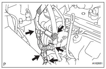
(a) Remove the terminal cap.
(b) Remove the nut and disconnect the wire harness from terminal B.
(c) Disconnect the generator connector from the generator assembly.
(d) Disconnect the connector from the compressor and magnetic clutch.
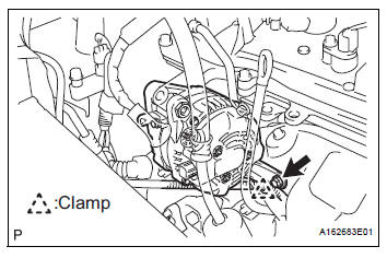
(e) Disconnect the 2 wire harness clamps.

(f) Remove the 2 bolts.
(g) Remove the bolt from the cylinder block.
(h) Disconnect the wire harness clamp and remove the generator assembly.

(i) Remove the bolt and wire harness clamp stay.

(j) Remove the bolt and bracket.
 Components
...
 Disassembly
1. REMOVE GENERATOR CLUTCH PULLEY
(A) using a screwdriver, remove the generator pulley
cap.
(b) Set SST (A) and (B).
SST 09820-63020
(c) Clamp SST (A) in a vise.
NOTICE:
...
Other materials:
Installation
1. INSTALL SHIFT LEVER ASSEMBLY
(a) Install shift lever assembly to the vehicle with the 4
bolts.
Torque: 21 N*m (214 kgf*cm, 15 ft.*lbf)
NOTICE:
Into datum hole of shift lever into datum pin of
instrument lower.
(b) Connect the 2 connectors to the shift lever
assembly.
...
Vehicle interior
Items
Check points
Accelerator pedal
The accelerator pedal should move
smoothly (without uneven pedal effort or
catching).
Automatic transaxle “Park”
mechanism
When parked on a slope with the shift
lever in P, is ...
Engine oil pressure switch
ON-VEHICLE INSPECTION
1. INSPECT ENGINE OIL PRESSURE SWITCH
ASSEMBLY
Disconnect the connector from the oil pressure
switch assembly.
With the switch still installed, measure the
resistance between the terminal of the engine oil
pressure switch and engine ground.
Standard ...
