Toyota Sienna Service Manual: Removal
1. Disconnect battery negative terminal
2. Remove instrument cluster finish panel sub-assembly center
Hint: (see page ip-9)
3. Remove transmission control cable assembly
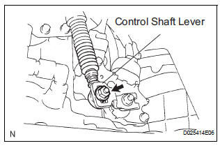
(a) Remove the nut from the control shaft lever.
(b) Disconnect the transmission control cable assembly from the control shaft lever.
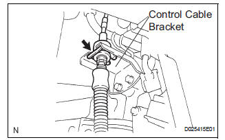
(c) Remove the clip and disconnect the transmission control cable assembly from the control cable bracket
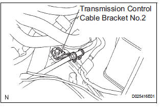
(d) Disconnect the transmission control cable assembly from the transmission control cable bracket No.2.
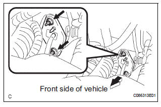
(e) Remove the 2 nuts and disconnect the transmission control cable assembly from the vehicle.
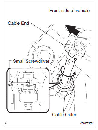
(f) Using a screwdriver, disconnect the cable end from the shift lever assembly (g) Using a small screwdriver, disconnect the cable outer of transmission control cable assembly from the shift lever assembly.
(h) Pull out the control cable from the vehicle.
 Transmission control cable assembly
COMPONENTS
...
 Adjustment
1. INSPECT SHIFT LEVER POSITION
(a) When shifting from P to R position only with ignition
switch ON and brake pedal, make sure that the
shifting lever moves smoothly and can be
moderately operated ...
Other materials:
Installation
1. INSTALL REAR NO. 2 SEAT ASSEMBLY RH
Place the rear No. 2 seat assembly RH in the cabin.
NOTICE:
Be careful not to damage the body.
Install the seat with the bolt.
Torque: 29 N*m (296 kgf*cm, 21 ft.*lbf)
Install the locus cable RH with the bolt.
Torque: 29 N*m ( ...
Removal
1. REMOVE REAR DOOR SCUFF PLATE
2. REMOVE REAR DOOR WEATHERSTRIP
3. REMOVE BACK DOOR WEATHERSTRIP
4. REMOVE BACK DOOR SCUFF PLATE
5. REMOVE FRONT QUARTER TRIM PANEL ASSEMBLY
Remove the floor anchor cover.
Remove the bolt and disconnect the No. 2 rear seat
outer belt assem ...
Passenger Side Outer Mirror ECU
DTC B1208 Passenger Side Outer Mirror ECU
DESCRIPTION
This DTC is detected when communication between the outer mirror control ECU
RH and multiplex
network gateway ECU stops for more than 10 seconds.
DTC No.
DTC Detecting Condition
Trouble Area
B1208
Pa ...
