Toyota Sienna Service Manual: Scratched / Reversed Disc
DTC 44-46 Scratched / Reversed Disc
DESCRIPTION
|
DTC No. |
DTC Detecting Condition |
Trouble Area |
|
44-46 |
Scratches or dirt is found on DVD surface or DVD is set upside down. |
|
INSPECTION PROCEDURE
HINT: After the inspection is completed, clear the DTCs.
1 CHECK THAT DISC IS INSERTED PROPERLY
- Check whether or not the disc is inserted upside down.
OK: Disc is properly inserted
2 CHECK DISC
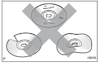
- Check that the disc is not deformed or cracked.
OK: No deformation or cracks on the disc.
3 DISC CLEANING
- Disc cleaning
- If dirt is on the disc surface, wipe it clean with a soft cloth from the inside to the outside in a radial direction.
NOTICE: Do not use a conventional record cleaner or anti-static preservative.
4 CLEAR DTC
- Clear the DTCs
5 RECHECK DTC
- Recheck for DTCs and check if the same trouble occurs again.
OK: Malfunction disappears.
6 REPLACE DISC WITH ANOTHER AND RECHECK
- Replace the disc with another and recheck.
- Replace the disc with another normal one.
- Clear the DTCs.
- Recheck for DTCs and check if the same trouble occurs again.
OK: Malfunction disappears.
END
 Eject Error/ Elevator Error/ Clamp Error
DTC 44-45 Eject Error
DTC 44-51 Elevator Error
DTC 44-52 Clamp Error
DESCRIPTION
DTC No.
DTC Detecting Condition
Trouble Area
44-45
Disc cannot be ejected.
...
 High Temperature
DTC 44-47 High Temperature
DESCRIPTION
DTC No.
DTC Detecting Condition
Trouble Area
44-47
Sensor detects that DVD unit temperature is high.
(Over 80C)
...
Other materials:
Unlocking and locking the doors from the inside
Door lock switch
Locks all the doors
Unlocks all the doors
Inside lock button
Locks the door
Unlocks the door
The front doors can be opened
by pulling the inside handle
even if the lock buttons are in
the lock position. ...
Front No. 2 speaker
COMPONENTS
ON-VEHICLE INSPECTION
1. INSPECT FRONT NO.2 SPEAKER
HINT:
Remove interior parts so that the front No.2 speaker can
be seen.
Check the speaker installation.
OK:
The speaker is securely installed.
If the result is not as specified, reinstall the front
No.2 speak ...
Terminals of ECU
1. COMBINATION METER ASSEMBLY
*1: with Power Rear No. 2 Seat with Stowing Function
*2: with Theft Deterrent System
Waveform 1 (Reference) : Using an oscilloscope:
OK:
HINT:
As vehicle speed increases, the cycle of the signal
waveform narrows.
Wavefor ...
