Toyota Sienna Service Manual: Sound Signal Circuit between Radio and Navigation Assembly and Stereo Component Amplifier
DESCRIPTION
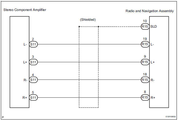
The radio and navigation assembly sends a sound signal to the stereo component amplifier through this circuit.
The sound signal that has been sent is amplified by the stereo component amplifier, and then is sent to the speakers.
If there is an open or short in the circuit, sound cannot be heard from the speakers even if there is no malfunction in the stereo component amplifier or speakers.
WIRING DIAGRAM
INSPECTION PROCEDURE
1 CHECK HARNESS AND CONNECTOR (RADIO AND NAVIGATION ASSEMBLY - STEREO COMPONENT AMPLIFIER)
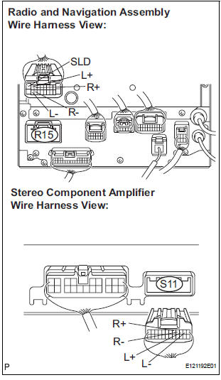
- Disconnect the connectors from the radio and navigation assembly and stereo component amplifier.
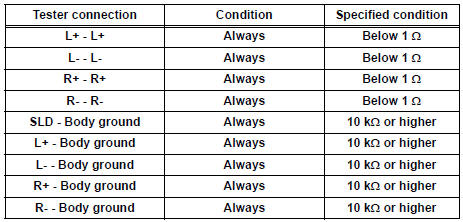
- Measure the resistance according to the value(s) in the table below.
Standard resistance
PROCEED TO NEXT CIRCUIT INSPECTION SHOWN IN PROBLEM SYMPTOMS TABLE
 Sound Signal Circuit between Radio and Navigation Assembly and
Television Display Assembly
Sound Signal Circuit between Radio and Navigation Assembly and
Television Display Assembly
DESCRIPTION
The television display assembly sends an RSE sound signal to the radio and
navigation assembly through
this circuit. The sound signal that has been sent is amplified by the stereo
co ...
 Sound Signal Circuit between Radio and Navigation Assembly and
Stereo Jack Adapter
Sound Signal Circuit between Radio and Navigation Assembly and
Stereo Jack Adapter
DESCRIPTION
The stereo jack adapter sends an external device sound signal to the radio
and navigation assembly
through this circuit.
The sound signal that has been sent is amplified by the ster ...
Other materials:
Installation
1. INSTALL DISTANCE CONTROL ECU ASSEMBLY
Using a torque wrench, install the bolt.
Torque: 5 N*m (51 kgf*cm, 44 in.*lbf)
NOTICE:
Do not install the dropped or shocked distance
control ECU assembly.
2. INITIALIZE DISTANCE CONTROL ECU
NOTICE:
After replacing the distance control ECU ...
Manual Up / Down and Auto Down Function does not Operate on
Passenger Side Only
DESCRIPTION
If the manual UP/DOWN function does not operate, the power window motor, the
regulator switch or the
wire harness may be malfunctioning.
WIRING DIAGRAM
INSPECTION PROCEDURE
1 CHECK WIRE HARNESS (POWER SOURCE)
Disconnect the P37 regulator switch connector.
Turn ...
Disassembly
1. REMOVE RADIATOR WATER INLET
(a) Remove the 2 bolts and radiator water inlet.
2. REMOVE DRAIN PLUG
(a) Remove the drain plug and air drain plug.
(b) Remove the 2 O-rings.
3. REMOVE LOWER RADIATOR TANK
(a) Install the claw to the overhaul handle, inserting it in
the hole in Part A ...
