Toyota Sienna Service Manual: Sound Signal Circuit between Radio and Navigation Assembly and Stereo Jack Adapter
DESCRIPTION
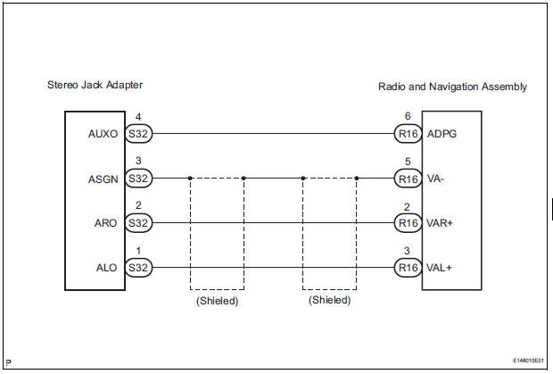
The stereo jack adapter sends an external device sound signal to the radio and navigation assembly through this circuit.
The sound signal that has been sent is amplified by the stereo component amplifier and then is sent to the speakers.
If there is an open or short in the circuit, sound cannot be heard from the speakers even if there is no malfunction in the stereo component amplifier radio and navigation assembly or speakers.
WIRING DIAGRAM
INSPECTION PROCEDURE
1 CHECK HARNESS AND CONNECTOR (RADIO AND NAVIGATION ASSEMBLY - STEREO JACK ADAPTER)
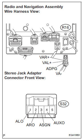
- Disconnect the connectors from the stereo jack adapter and radio and navigation assembly.
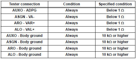
- Measure the resistance according to the value(s) in the table below.
Standard resistance
PROCEED TO NEXT CIRCUIT INSPECTION SHOWN IN PROBLEM SYMPTOMS TABLE
 Sound Signal Circuit between Radio and Navigation Assembly and
Stereo Component Amplifier
Sound Signal Circuit between Radio and Navigation Assembly and
Stereo Component Amplifier
DESCRIPTION
The radio and navigation assembly sends a sound signal to the stereo
component amplifier through this
circuit.
The sound signal that has been sent is amplified by the stereo compone ...
 Mute Signal Circuit between Radio and Navigation Assembly and
Television Display Assembly
Mute Signal Circuit between Radio and Navigation Assembly and
Television Display Assembly
DESCRIPTION
The radio and navigation assembly controls the volume according to the MUTE
signal from the television
display assembly.
The MUTE signal is sent to reduce noise and a popping sound ...
Other materials:
Removal
1. REMOVE REAR WHEEL
2. REMOVE REAR SHOCK ABSORBER CAP LH
(a) Remove the shock absorber head cover.
(b) Remove the shock absorber cap LH.
3. REMOVE SHOCK ABSORBER ASSEMBLY REAR LH
(a) Support the rear axle beam with a jack.
(b) Using a 6 mm hexagon wrench to hold the piston
rod, ...
Short to B+ in Curtain Shield Squib LH Circuit
DTC B1168/86 Short to B+ in Curtain Shield Squib LH Circuit
DESCRIPTION
The curtain shield squib LH circuit consists of the center airbag sensor
assembly and the curtain shield
airbag assembly LH.
The circuit instructs the SRS to deploy when deployment conditions are met.
DTC B1168/86 is ...
Power Windows do not Operate at All
DESCRIPTION
If all of the door windows do not operate, no power may be supplied to the
power window master switch or
the power window master switch itself may have a malfunction.
WIRING DIAGRAM
INSPECTION PROCEDURE
1 INSPECT FUSE (PWR, ECU-IG, AM1)
Remove the fuses from the driver sid ...
