Toyota Sienna Service Manual: Sound Signal Circuit between Radio Receiver and Stereo Component Amplifier
DESCRIPTION
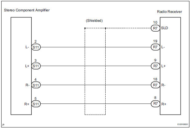
The radio receiver sends a sound signal to the stereo component amplifier through this circuit.
The sound signal that has been sent is amplified by the stereo component amplifier, and then is sent to the speakers.
If there is an open or short in the circuit, sound cannot be heard from the speakers even if there is no malfunction in the stereo component amplifier or speakers.
WIRING DIAGRAM
INSPECTION PROCEDURE
1 CHECK HARNESS AND CONNECTOR (RADIO RECEIVER - STEREO COMPONENT AMPLIFIER)
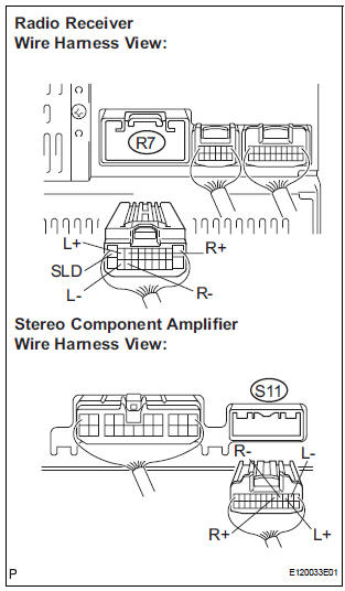
- Disconnect the connectors from the radio receiver and stereo component amplifier.
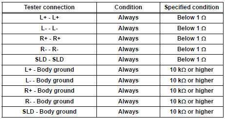
- Measure the resistance according to the value(s) in the table below.
Standard resistance
PROCEED TO NEXT CIRCUIT INSPECTION SHOWN IN PROBLEM SYMPTOMS TABLE
 Speaker Circuit
DESCRIPTION
When the vehicle has a built-in type amplifier, a sound signal is
sent from the radio receiver to the
speakers via the "6 Speaker System" circuit.
When the ...
 Sound Signal Circuit between Radio Receiver and Television Display
Assembly
Sound Signal Circuit between Radio Receiver and Television Display
Assembly
DESCRIPTION
The television display assembly sends a sound signal to the radio receiver
through this circuit.
The sound signal that has been sent is amplified by the stereo component
amplifier ...
Other materials:
Insufficient Coolant Temperature for Closed
Loop Fuel Control
DTC P0125 Insufficient Coolant Temperature for Closed
Loop Fuel Control
DESCRIPTION
Refer to DTC P0115
DTC No.
DTC Detection Condition
Trouble Area
P0125
Engine coolant temperature (ECT) does not reach
closed-loop enabling temperature for 20 minutes (t ...
Communication Error from ECM to VSC
DTC P1631 Communication Error from ECM to VSC
DTC U0100 Lost Communication with ECM/PCM "A"
DESCRIPTION
The ECM sends signals such as A/T information signals, dynamic laser cruise
control operation signals,
brake operation demand signals, and buzzer operation demand signals to the sk ...
Removal
1. REMOVE FRONT WHEELS
2. REMOVE ENGINE UNDER COVER NO.1
3. DRAIN AUTOMATIC TRANSAXLE FLUID
(a) Remove the drain plug, gasket and drain ATF.
(b) Install a new gasket and the drain plug.
Torque: 49 N*m (500 kgf*cm, 36 ft.*lbf)
4. REMOVE FRONT DRIVE SHAFT ASSEMBLY LH
HINT:
(See page DS-6)
...
